7.13 Electromagnetic Compatibility (EMC) Overview
Electrical devices both generate interference and are aected by interference from other generated sources. The electro-
magnetic compatibility (EMC) of these eects depends on the power and the harmonic characteristics of the devices.
Uncontrolled interaction between electrical devices in a system can degrade compatibility and impair reliable operation.
Interference takes the form of the following:
•
Electrostatic discharges.
•
Rapid voltage
uctuations.
•
High-frequency interference.
Electrical interference is most commonly found at frequencies in the range 150 kHz to 30 MHz. Airborne interference from
the drive system in the range 30 MHz to 1 GHz is generated from the inverter, motor cable, and the motor.
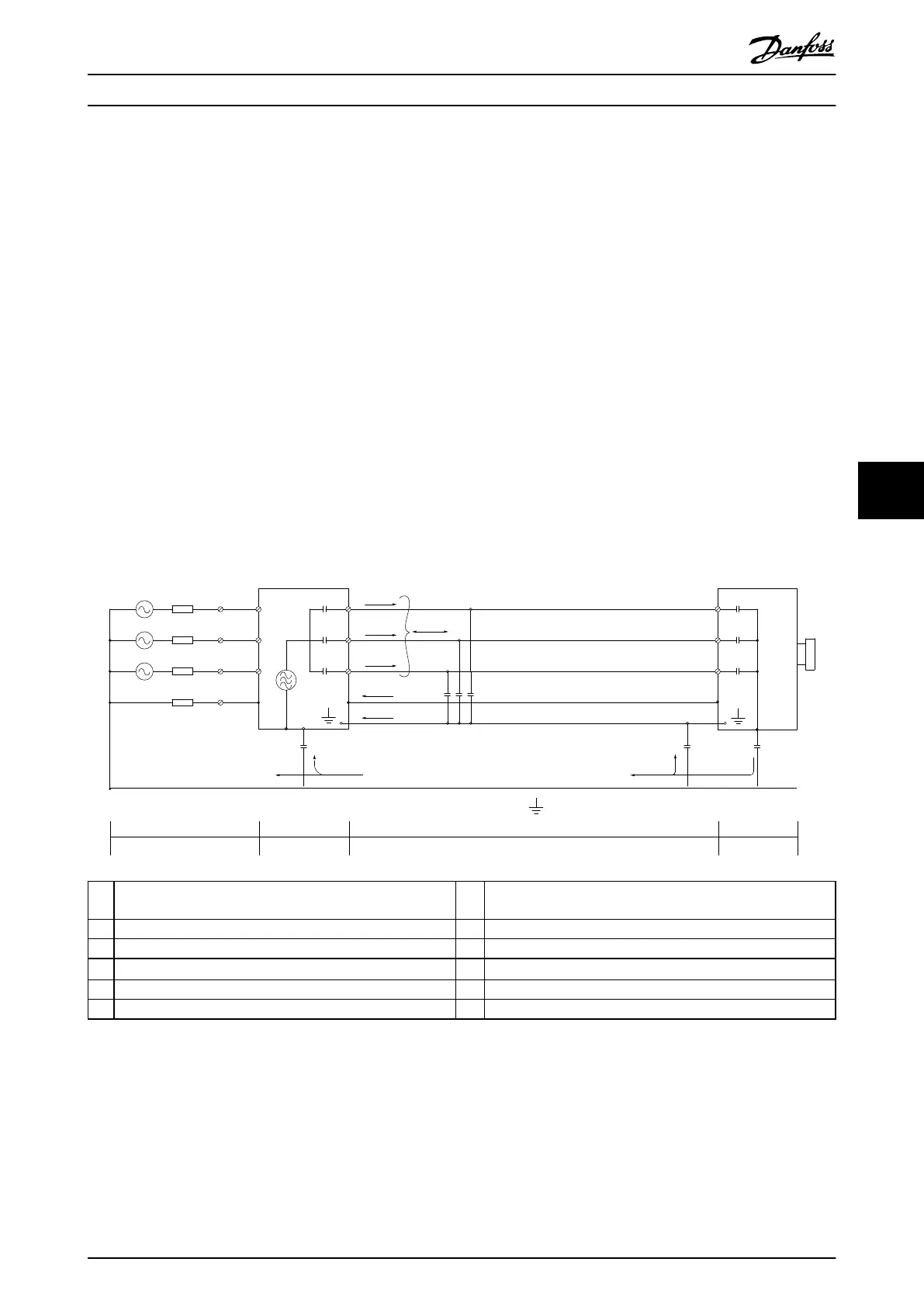
Capacitive currents in the motor cable, coupled with a high dU/dt from the motor voltage, generate leakage currents. See
Illustration 7.16. Shielded motor cables have higher capacitance between the phase wires and the shield, and again between
the shield and ground. This added cable capacitance, along with other parasitic capacitance and motor inductance, changes
the electromagnetic emission signature produced by the unit. The change in electromagnetic emission signature occurs
mainly in emissions less than 5 MHz. Most of the leakage current (I1) is carried back to the unit through the PE (I3), leaving
only a small electromagnetic
eld (I4) from the shielded motor cable. The shield reduces the radiated interference but
increases the low-frequency interference on the mains.
1
2
z
z
z
L1
L2
L3
PE
U
V
W
C
S
I
2
I
1
I
3
I
4
C
S
C
S
C
S
C
S
I
4
C
S
z
PE
3
4
5
6
1 Ground wire Cs Possible shunt parasitic capacitance paths (varies with dierent
installations)
2 Shield I
1
Common-mode leakage current
3 AC mains supply I
2
Shielded motor cable
4 Drive I
3
Safety ground (4
th
conductor in motor cables)
5 Shielded motor cable I
4
Unintended common-mode current
6 Motor – –
Illustration 7.16 Electric Model Showing Possible Leakage Currents
Electrical Installation Con... Design Guide
MG06K102 Danfoss A/S © 03/2019 All rights reserved. 51
7 7
 Loading...


