7.6 Motor
Any 3-phase asynchronous standard motor can be used
with a drive.
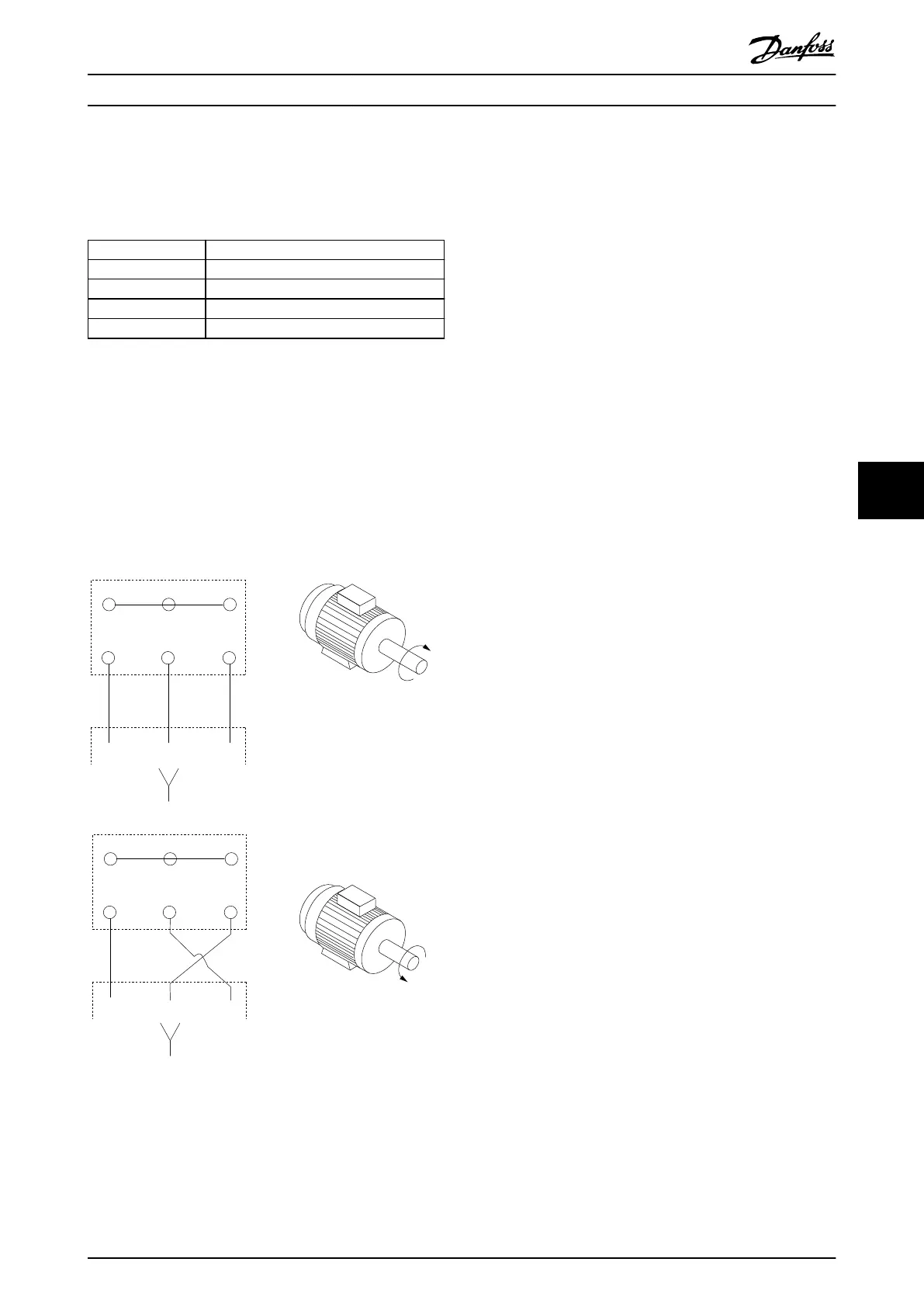
Terminal Function
96 U/T1
97 V/T2
98 W/T3
99 Ground
Table 7.9 Motor Cable Terminals Providing Clockwise
Rotation (Factory Default)
The direction of rotation can be changed by switching 2
phases in the motor cable, or by changing the setting of
parameter 4-10 Motor Speed Direction.
Motor rotation check can be performed using
parameter 1-28 Motor Rotation Check and following the
conguration shown in Illustration 7.9.
175HA036.11
U
1
V
1
W
1
96 97 98
FC
Motor
U
2
V
2
W
2
U
1
V
1
W
1
96 97 98
FC
Motor
U
2
V
2
W
2
Illustration 7.9 Changing Motor Rotation
7.6.1 Motor Thermal Protection
The electronic thermal relay in the drive has received
approval for single motor overload protection, when
parameter 1-90 Motor Thermal Protection is set for ETR Trip
and parameter 1-24 Motor Current is set to the rated motor
current (see the motor nameplate).
7.6.2 Parallel Connection of Motors
The drive can control several parallel-connected motors.
For dierent congurations of parallel-connected motors,
see Illustration 7.10.
When using parallel motor connection, observe the
following points:
•
Run applications with parallel motors in U/F
mode (volts per hertz).
•
VVC
+
mode can be used in some applications.
•
Total current consumption of motors must not
exceed the rated output current I
INV
for the drive.
•
Problems can occur at start and at low RPM if
motor sizes are widely dierent because the
relatively high ohmic resistance in the stator of a
small motor demands a higher voltage at start
and at low RPM.
•
The electronic thermal relay (ETR) of the drive
cannot be used as motor overload protection.
Provide further motor overload protection by
including thermistors in each motor winding or
individual thermal relays.
•
When motors are connected in parallel,
parameter 1-01 Motor Control Principle must be set
to [0] U/f.
Electrical Installation Con... Design Guide
MG06K102 Danfoss A/S © 03/2019 All rights reserved. 45
7 7
 Loading...


