130BA062.14
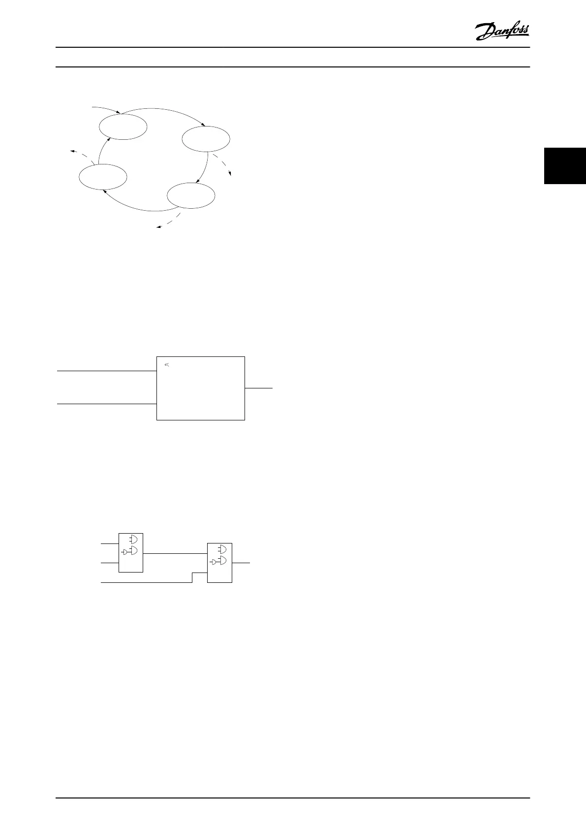
State 1
13-51.0
13-52.0
State 2
13-51.1
13-52.1
Start
event P13-01
State 3
13-51.2
13-52.2
State 4
13-51.3
13-52.3
Stop
event P13-02
Stop
event P13-02
Stop
event P13-02
Illustration 3.3 Order of Execution when 4 Events/Actions are
Programmed
Comparators
Comparators are used for comparing continuous variables
(output frequency, output current, analog input, and so on)
to xed preset values.
Par. 13-11
Comparator Operator
=
TRUE longer than.
. . .
. . .
Par. 13-10
Comparator Operand
Par. 13-12
Comparator Value
130BB672.10
Illustration 3.4 Comparators
Logic rules
Combine up to 3 boolean inputs (TRUE/FALSE inputs) from
timers, comparators, digital inputs, status bits, and events
using the logical operators AND, OR, and NOT.
. . .
. . .
. . .
. . .
Par. 13-43
Logic Rule Operator 2
Par. 13-41
Logic Rule Operator 1
Par. 13-40
Logic Rule Boolean 1
Par. 13-42
Logic Rule Boolean 2
Par. 13-44
Logic Rule Boolean 3
130BB673.10
Illustration 3.5 Logic Rules
3.4 Dynamic Braking Overview
Dynamic braking slows the motor using 1 of the following
methods:
•
AC brake
The brake energy is distributed in the motor by
changing the loss conditions in the motor
(parameter 2-10 Brake Function = [2]). The AC
brake function cannot be used in applications
with high cycling frequency since this situation
overheats the motor.
•
DC brake
An overmodulated DC current added to the AC
current works as an eddy current brake
(parameter 2-02 DC Braking Time ≠ 0 s).
Product Overview and Featur... Design Guide
MG06K102 Danfoss A/S © 03/2019 All rights reserved. 13
3 3
 Loading...


