11.11.4 Control Word According to
PROFIdrive Prole (CTW)
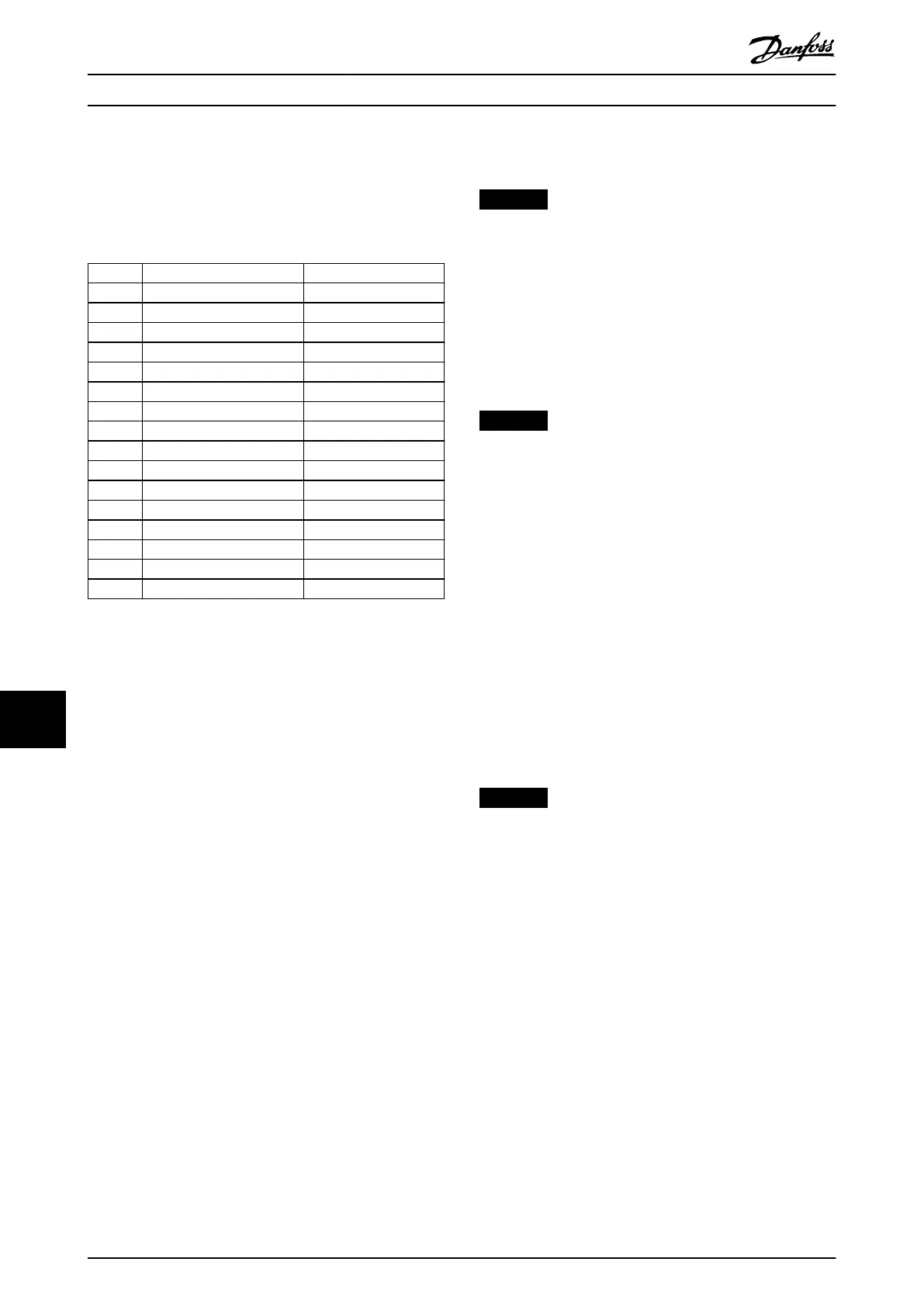
The control word is used to send commands from a master
to a slave.
Bit Bit=0 Bit=1
00 OFF 1 ON 1
01 OFF 2 ON 2
02 OFF 3 ON 3
03 Coasting No coasting
04 Quick stop Ramp
05 Hold frequency output Use ramp
06 Ramp stop Start
07 No function Reset
08 Jog 1 OFF Jog 1 ON
09 Jog 2 OFF Jog 2 ON
10 Data invalid Data valid
11 No function Slow down
12 No function Catch up
13 Parameter set-up Selection lsb
14 Parameter set-up Selection msb
15 No function Reverse
Table 11.22 Bit Values for Control Word, PROFIdrive Prole
Explanation of the control bits
Bit 00, OFF 1/ON 1
Normal ramp stops using the ramp times of the actual
selected ramp.
Bit 00=0 leads to the stop and activation of the output
relay 1 or 2 if the output frequency is 0 Hz and if [31] Relay
123 has been selected in parameter 5-40 Function Relay.
When bit 00=1, the drive is in State 1: Switching on
inhibited.
Bit 01, OFF 2/ON 2
Coasting stop
When bit 01=0, a coasting stop and activation of the
output relay 1 or 2 occurs if the output frequency is 0 Hz
and if [31] Relay 123 has been selected in
parameter 5-40 Function Relay.
When bit 01=1, the drive is in State 1: on inhibited. Refer
to Table 11.23 at the end of this section.
Bit 02, OFF 3/ON 3
Quick stop using the ramp time of parameter 3-81 Quick
Stop Ramp Time.
When bit 02=0, a quick stop and activation of the output
relay 1 or 2 occurs if the output frequency is 0 Hz and if
[31] Relay 123 has been selected in parameter 5-40 Function
Relay.
When bit 02=1, the drive is in State 1: Switching on
inhibited.
Bit 03, Coasting/No coasting
Coasting stop bit 03=0 leads to a stop.
When bit 03=1, the drive can start if the other start
conditions are satised.
NOTICE
The selection in parameter 8-50 Coasting Select
determines how bit 03 is linked with the corresponding
function of the digital inputs.
Bit 04, Quick stop/Ramp
Quick stop using the ramp time of parameter 3-81 Quick
Stop Ramp Time.
When bit 04=0, a quick stop occurs.
When bit 04=1, the drive can start if the other start
conditions are satised.
NOTICE
The selection in parameter 8-51 Quick Stop Select
determines how bit 04 is linked with the corresponding
function of the digital inputs.
Bit 05, Hold frequency output/Use ramp
When bit 05=0, the current output frequency is being
maintained even if the reference value is
modied.
When bit 05=1, the drive can perform its regulating
function again; operation occurs according to the
respective reference value.
Bit 06, Ramp stop/Start
Normal ramp stop using the ramp times of the actual
ramp as selected. In addition, activation of the output relay
01 or 04 if the output frequency is 0 Hz if [31] Relay 123
has been selected in parameter 5-40 Function Relay.
Bit 06=0 leads to a stop.
When bit 06=1, the drive can start if the other start
conditions are fullled.
NOTICE
The selection in parameter 8-53 Start Select determines
how bit 06 is linked with the corresponding function of
the digital inputs.
Bit 07, No function/Reset
Reset after switching o.
Acknowledges event in fault buer.
When bit 07=0, no reset occurs.
When there is a slope change of bit 07 to 1, a reset occurs
after switching o.
Bit 08, Jog 1 OFF/ON
Activates the pre-programmed speed in parameter 8-90 Bus
Jog 1 Speed. JOG 1 is only possible if bit 04=0 and bit 00–
03=1.
Bit 09, Jog 2 OFF/ON
Activates the pre-programmed speed in parameter 8-91 Bus
Jog 2 Speed. JOG 2 is only possible if bit 04=0 and bit 00–
03=1.
Bit 10, Data invalid/valid
Tells the drive whether the control word should be used or
ignored.
Appendix VLT® AutomationDrive FC 361
92 Danfoss A/S © 03/2019 All rights reserved. MG06K102
1111
 Loading...


