13-20 SL Controller Timer
Range: Function:
74] Start timer X) and until the
timer value has elapsed. Array
parameters contain timers 0–7.
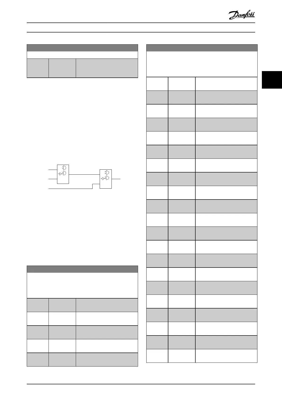
3.9.5 13-4* Logic Rules
Combine up to 3 boolean inputs (true/false inputs) from
timers, comparators, digital inputs, status bits, and events
using the logical operators AND, OR, and NOT. Select
boolean inputs for the calculation in parameter 13-40 Logic
Rule Boolean 1, parameter 13-42 Logic Rule Boolean 2, and
parameter 13-44 Logic Rule Boolean 3. Dene the operators
used to combine the selected inputs logically in
parameter 13-41 Logic Rule Operator 1 and
parameter 13-43 Logic Rule Operator 2.
. . .
. . .
. . .
. . .
Par. 13-43
Logic Rule Operator 2
Par. 13-41
Logic Rule Operator 1
Par. 13-40
Logic Rule Boolean 1
Par. 13-42
Logic Rule Boolean 2
Par. 13-44
Logic Rule Boolean 3
130BB673.10
Illustration 3.13 Logic Rules
Priority of calculation
The results of parameter 13-40 Logic Rule Boolean 1,
parameter 13-41 Logic Rule Operator 1, and
parameter 13-42 Logic Rule Boolean 2 are calculated rst.
The outcome (true/false) of this calculation is combined
with the settings of parameter 13-43 Logic Rule Operator 2
and parameter 13-44 Logic Rule Boolean 3, yielding the nal
result (true/false) of the logic rule.
13-40 Logic Rule Boolean 1
Array [6]
Select the rst boolean (TRUE or FALSE) input for the selected
logic rule.
Option: Function:
[0] * False Enters the xed value of FALSE in
the logic rule.
[1] True Enters the xed value TRUE in the
logic rule.
[2] Running See parameter 13-01 Start Event for
further description.
[3] In range See parameter 13-01 Start Event for
further description.
[4] On reference See parameter 13-01 Start Event for
further description.
13-40 Logic Rule Boolean 1
Array [6]
Select the rst boolean (TRUE or FALSE) input for the selected
logic rule.
Option: Function:
[7] Out of current
range
See parameter 13-01 Start Event for
further description.
[8] Below I low See parameter 13-01 Start Event for
further description.
[9] Above I high See parameter 13-01 Start Event for
further description.
[16] Thermal
warning
See parameter 13-01 Start Event for
further description.
[17] Mains out of
range
See parameter 13-01 Start Event for
further description.
[18] Reversing See parameter 13-01 Start Event for
further description.
[19] Warning See parameter 13-01 Start Event for
further description.
[20] Alarm (trip) See parameter 13-01 Start Event for
further description.
[21] Alarm (trip
lock)
See parameter 13-01 Start Event for
further description.
[22] Comparator 0 Use the result of comparator 0 in
the logic rule.
[23] Comparator 1 Use the result of comparator 1 in
the logic rule.
[24] Comparator 2 Use the result of comparator 2 in
the logic rule.
[25] Comparator 3 Use the result of comparator 3 in
the logic rule.
[26] Logic rule 0 Use the result of logic rule 0 in the
logic rule.
[27] Logic rule 1 Use the result of logic rule 1 in the
logic rule.
[28] Logic rule 2 Use the result of logic rule 2 in the
logic rule.
[29] Logic rule 3 Use the result of logic rule 3 in the
logic rule.
[30] SL Time-out 0 Use the result of timer 0 in the
logic rule.
[31] SL Time-out 1 Use the result of timer 1 in the
logic rule.
[32] SL Time-out 2 Use the result of timer 2 in the
logic rule.
[33] Digital input
DI18
Use the value of DI18 in the logic
rule (High=TRUE).
Parameters Programming Guide
MG18P202 Danfoss A/S © 06/2019 All rights reserved. 49
3 3
 Loading...


