3. 6 pole analog I/O
4. USB Connection
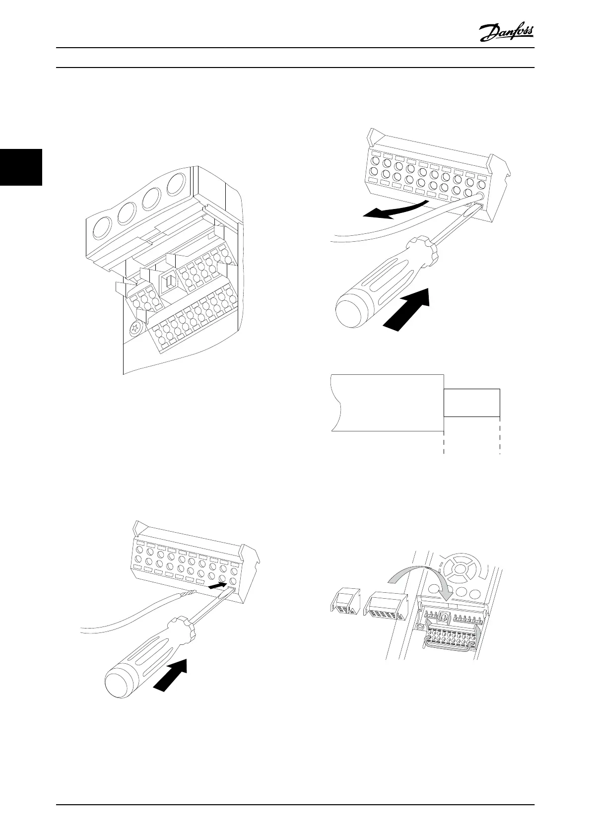
Control terminals are located beneath the LCP. The inside
of the removable cover shows the terminals.
1
4
2
3
130BA012.11
61
68
69
39
42
50
53
54
55
12
13
18
19
27
29
32
33
20
37
Illustration 3.18 Control Terminals
To mount the cable to the terminal:
1. Strip isolation of 9-10 mm
2. Insert a screwdriver in the square hole.
3. Insert the cable in the adjacent circular hole.
4. Remove the screwdriver. The cable is now
mounted to the terminal
Illustration 3.19
To remove the cable from the terminal:
1. Insert a screwdriver in the square hole.
2. Pull out the cable
Illustration 3.20
130BA150.10
9 - 10 mm
(0.37 in)
Illustration 3.21
3.3.10 Basic Wiring Example
1. Mount terminals from the accessory bag to the
front of the frequency converter.
Illustration 3.22
2. Connect terminals 18, 27 and 37 to +24 V
(terminal 12/13)
Default settings:
18 = start
27 = coast inverse
How to Install
Operating Instructions VLT
®
CDS302 and CDS303
22 MG34M302 - VLT
®
is a registered Danfoss trademark/Commercial Compressor
3
3