5.1.4 Indicator Lights
If certain threshold values are exceeded, the alarm and/or
warning LED lights up. A status and alarm text appear on
the control panel. The on LED is activated when the
frequency converter receives mains voltage.
•
Green LED/On: Control section is working.
•
Yellow LED/Warn.: Indicates a warning.
•
Flashing Red LED/Alarm: Indicates an alarm
Illustration 5.2
5.2 LCP Keys
5.2.1 Function Keys
The control keys are divided into functions. The keys
below the display and indicator lamps are used for
parameter Set-up, including choice of display indication
during normal operation.
130BP045.10
Status
Quick
Menu
Main
Menu
Alarm
Log
Illustration 5.3
[Status] indicates the status of the frequency converter
and/or the compressor motor. Choose between 3 different
readouts by pressing the [Status] key: 5 line readouts, 4
line readouts or Smart Logic Control by pushing [Status]
twice.
Press [Status] to select the display mode or to change back
to Display mode from either Quick Menu mode, Main
Menu mode or Alarm mode. Also press [Status] to toggle
single or double read-out mode.
[Quick Menu] allows quick access to different Quick Menus
such as:
Q1 - My Personal Menu
Q2 - Quick Set-up
Q3 – PID Process Loop
Q4 - Compressor Functions
Q5 - Changes Made
Q6 - Loggings
Q7 - Load Profile
Use [Quick Menu] for programming the parameters
belonging to the Quick Menu. It is possible to switch
directly between Quick Menu mode and Main Menu mode.
5.2.2 Navigation Keys
The four navigation keys are used to navigate between the
different choices available in [Quick Menu], [Main Menu]
and [Alarm Log]. Use the keys to move the cursor.
[OK] is used for choosing a parameter marked by the
cursor and for enabling the change of a parameter and
loggings from Quick Menu.
5.2.3
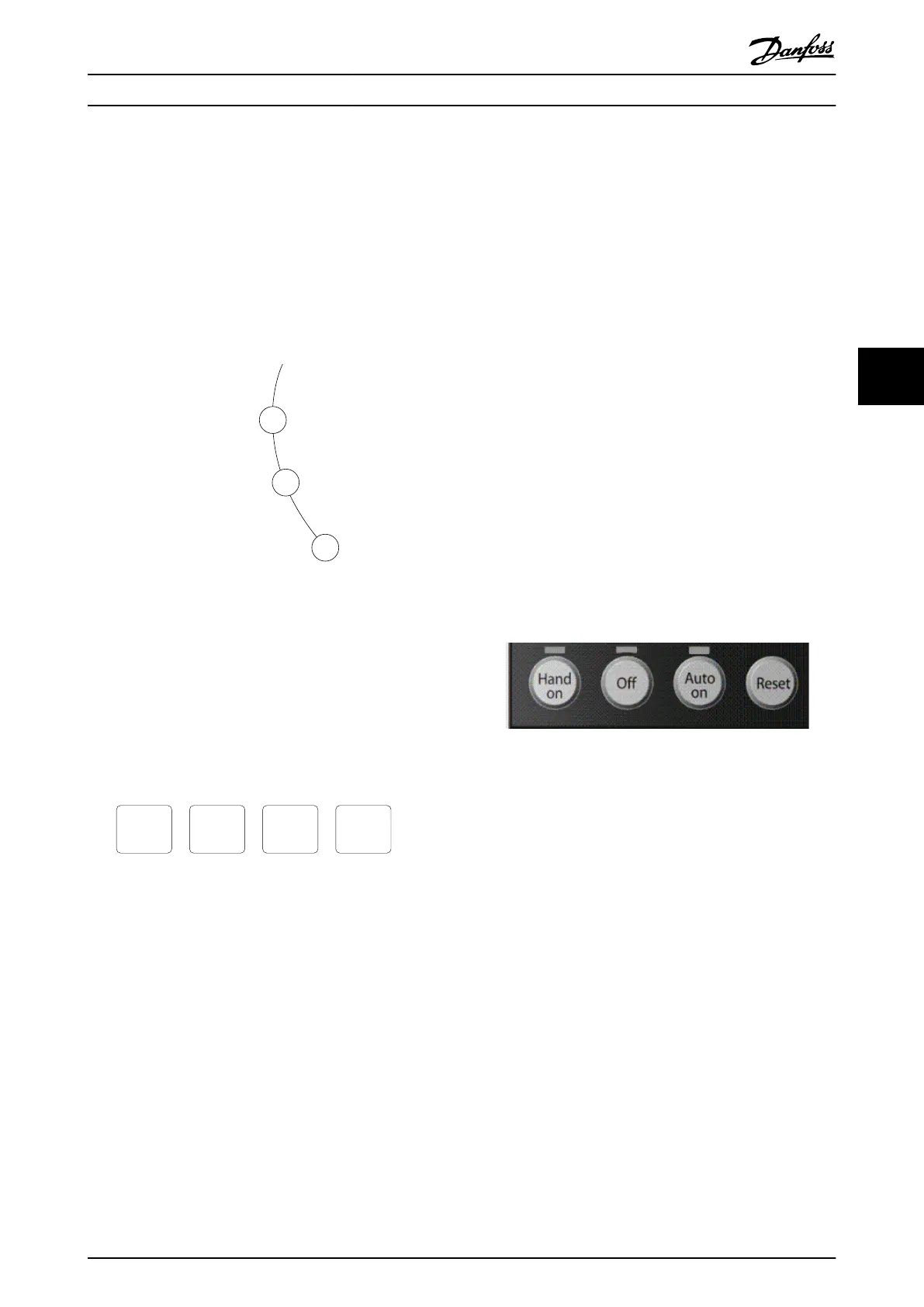
Local Control Keys
Local Control Keys for local control are found at the
bottom of the control panel.
Illustration 5.4
[Hand On] enables control of the frequency converter via
the LCP. [Hand on] also starts the motor compressor, and it
is now possible to enter the motor compressor speed data
by means of the arrow keys. The key can be selected as [1]
Enable or [0] Disable via 0-40 [Hand on] Key on LCP.
External stop signals activated by means of control signals
or a serial bus will override a “start“ command via the LCP.
The following control signals will still be active when
[Hand on] is activated:
•
[Hand On] - [Off] - [Auto On]
•
Reset
•
Coasting stop inverse
•
Reversing
•
Set-up select lsb (least significant bit) - Set-up
select msb (most significant bit)
•
Stop command from serial communication
•
Quick stop
•
DC brake
How to Program
Operating Instructions VLT
®
CDS302 and CDS303
MG34M302 - VLT
®
is a registered Danfoss trademark/Commercial Compressor 41
5 5