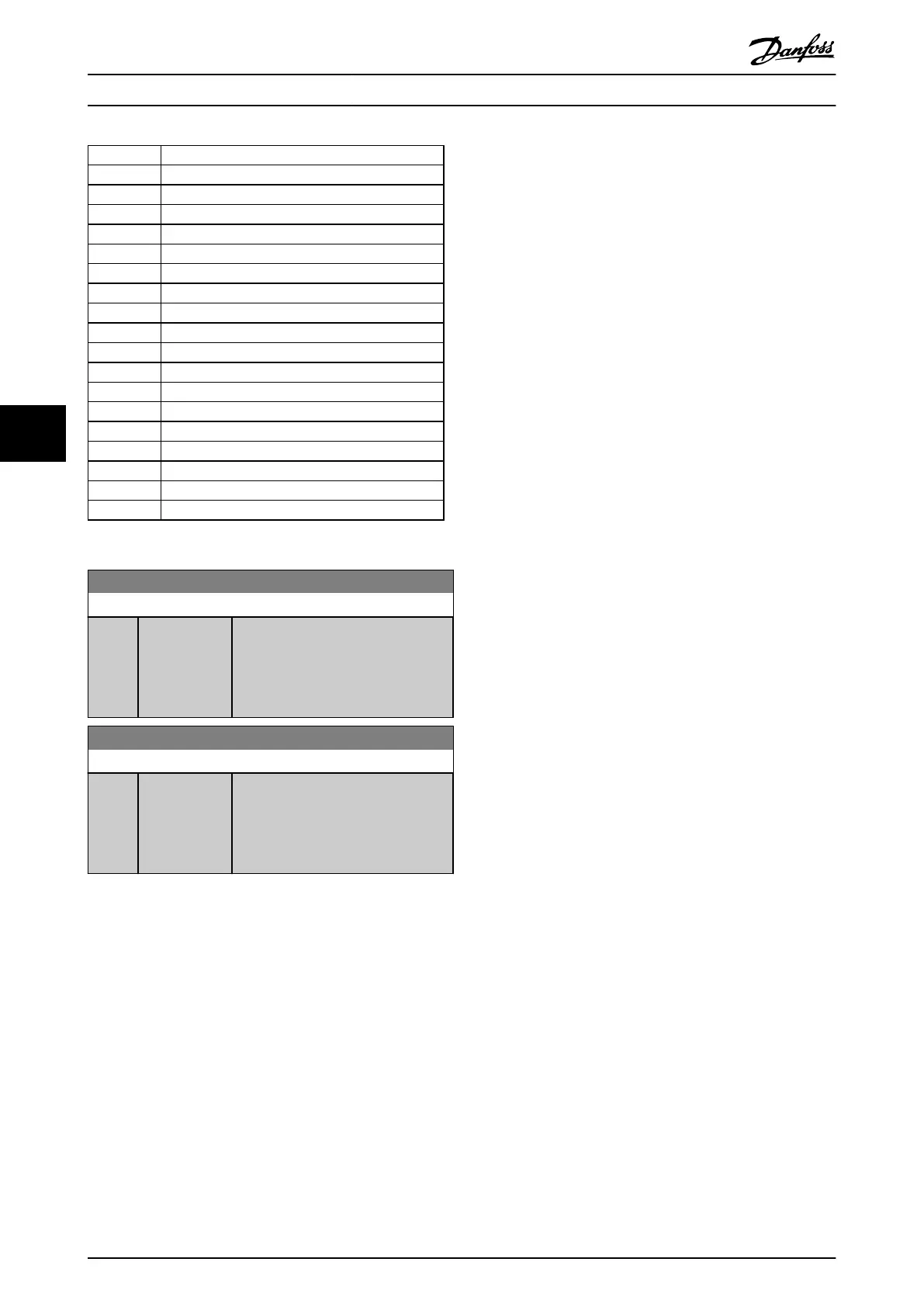
Bit 0 Digital Output Terminal 27
Bit 1 Digital Output Terminal 29
Bit 2 Digital Output Terminal X 30/6
Bit 3 Digital Output Terminal X 30/7
Bit 4 Relay 1 output terminal
Bit 5 Relay 2 output terminal
Bit 6 Option B Relay 1 output terminal
Bit 7 Option B Relay 2 output terminal
Bit 8 Option B Relay 3 output terminal
Bit 9-15 Reserved for future terminals
Bit 16 Option C Relay 1 output terminal
Bit 17 Option C Relay 2 output terminal
Bit 18 Option C Relay 3 output terminal
Bit 19 Option C Relay 4 output terminal
Bit 20 Option C Relay 5 output terminal
Bit 21 Option C Relay 6 output terminal
Bit 22 Option C Relay 7 output terminal
Bit 23 Option C Relay 8 output terminal
Bit 24-31 Reserved for future terminals
Table 6.8
5-93 Pulse Out #27 Bus Control
Range: Function:
0.00 %* [0.00 - 100.00
%]
Set the output frequency transferred to
the output terminal 27 when the
terminal is configured as [45] Bus
Controlled in 5-60 Terminal 27 Pulse
Output Variable.
5-95 Pulse Out #29 Bus Control
Range: Function:
0.00 %* [0.00 - 100.00
%]
Set the output frequency transferred to
the output terminal 29 when the
terminal is configured as [45] Bus
Controlled in 5-63 Terminal 29 Pulse
Output Variable.
Parameter Descriptions
Operating Instructions VLT
®
CDS302 and CDS303
68 MG34M302 - VLT
®
is a registered Danfoss trademark/Commercial Compressor
6
6