4 Connection
4.1 Soft Starter Connection
The EtherNet/IP Module is powered from the soft starter.
VLT
®
Compact Starter MCD 201/MCD 202
For the EtherNet/IP Module to accept eldbus commands, t a link across terminals A1–N2 on the soft starter.
VLT
®
Soft Starter MCD 500
If the MCD 500 has to be operated in remote mode, input links are required across terminals 17 and 25 to terminal 18. In
hand-on mode, links are not required.
NOTICE
FOR MCD 500 ONLY
Control via the eldbus communication network is always enabled in local control mode and can be enabled or
disabled in remote control mode (parameter 3-2 Comms in Remote). See the VLT
®
Soft Starter MCD 500 Operating Guide
for parameter details.
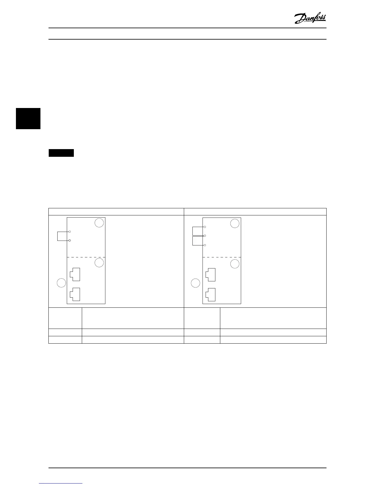
EtherNet/IP Module Connections
MCD 201/202 MCD 500
1 A1, N2: Stop input 1 (Auto-on mode)
17, 18: Stop input
25, 18: Reset input
2 EtherNet/IP Module 2 EtherNet/IP Module
3 RJ45 Ethernet ports 3 RJ45 Ethernet ports
Table 4.1 Connection Diagrams
Connection EtherNet/IP Module
8 Danfoss A/S © 05/2017 All rights reserved. MG17Q102
44