EasyManuals Logo

Danfoss vlt FC 102 User Guide

Danfoss vlt FC 102
82 pages
To Next Page IconTo Next Page
To Previous Page IconTo Previous Page
Page #32 background imageLoading...
Page #32 background image
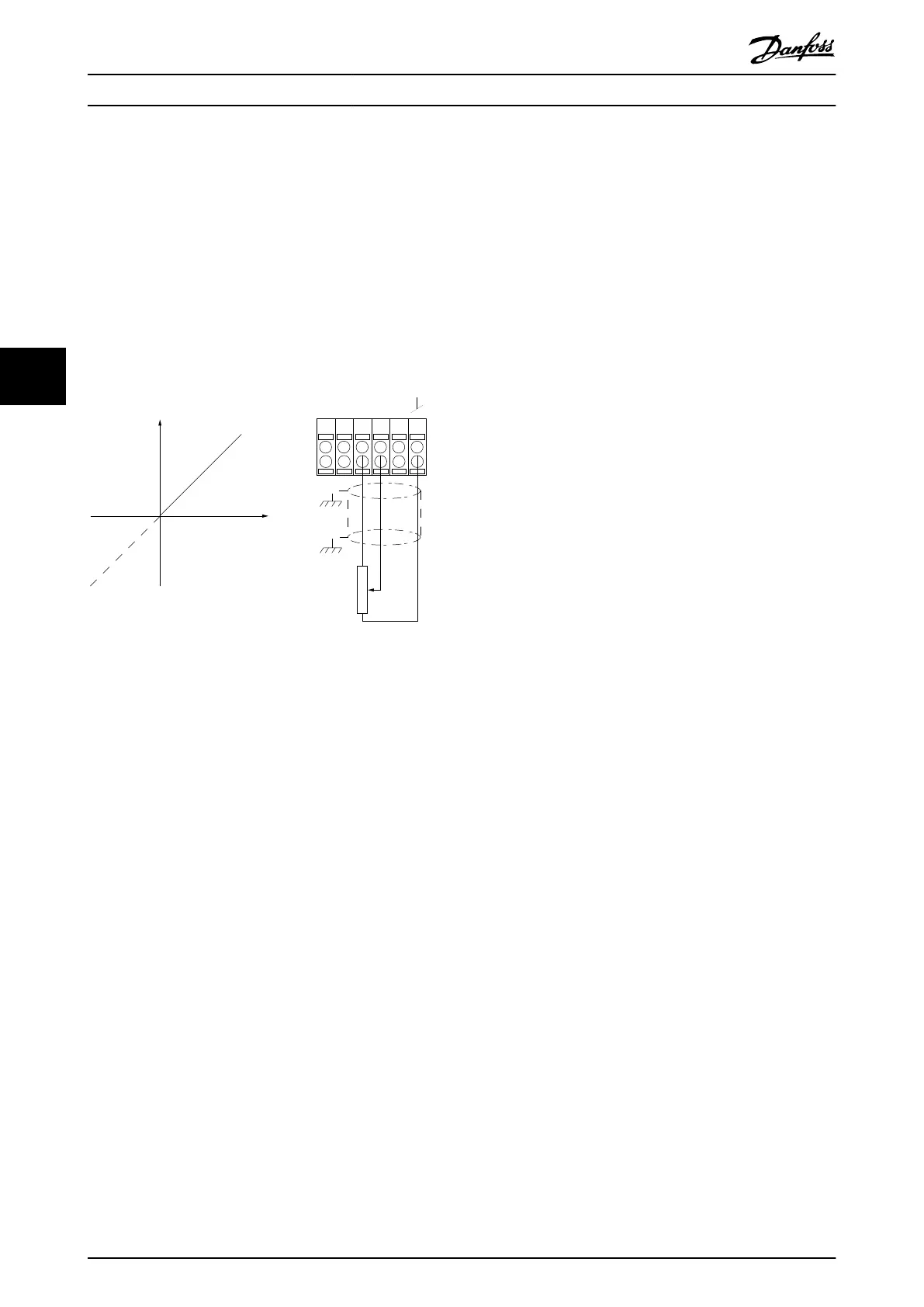
5.3.4 Potentiometer Reference
Voltage reference via a potentiometer
Reference source 1 = [1] Analog input 53 (default).
Terminal 53, Low voltage = 0 V.
Terminal 53, High voltage = 10 V.
Terminal 53, Low ref./feedback = 0 RPM.
Terminal 53, High ref./feedback = 1500 RPM.
Switch S201 = OFF (U).
130BA154.11
555039 42 53 54
Speed RPM
P 6-15
1 kΩ
+10V/30mA
Ref. voltage
P 6-11 10V
Illustration 5.8 Potentiometer Voltage Reference
Application Set-up Examples
VLT
®
Parallel Drive Modules
30 Danfoss A/S © 08/2017 All rights reserved. MG37L202
55

Table of Contents

Other manuals for Danfoss vlt FC 102

Questions and Answers:

Question and Answer IconNeed help?

Do you have a question about the Danfoss vlt FC 102 and is the answer not in the manual?

Danfoss vlt FC 102 Specifications

General IconGeneral
CategoryDC Drives
ModelDanfoss VLT FC 102
Output voltage range0 to rated motor voltage
Power range0.37 kW to 200 kW
Communication interfacesRS-485
Protection featuresOvervoltage, undervoltage, overcurrent, short circuit, earth fault, overtemperature, motor thermal protection
Cooling methodAir-cooled
Enclosure ratingIP20, IP21, IP55 (depending on model)
ApprovalsCE, UL, cUL

Related product manuals