6.7.2 Conguring the Drive System for Reduced Power Mode
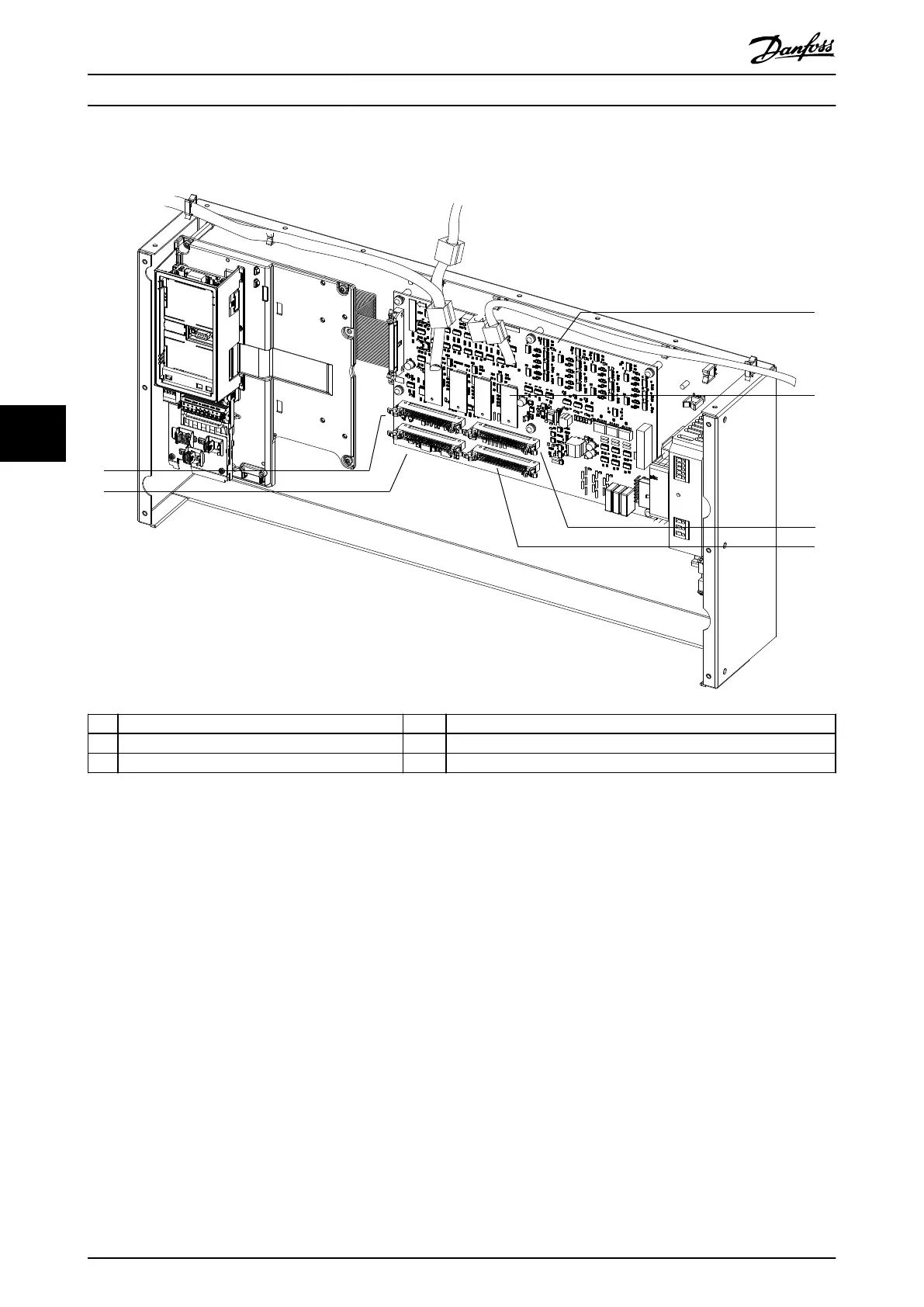
1 44-pin connector (MK111) 4 Scaling card (1 of 4)
2 44-pin connector (MK112) 5 44-pin connector (MK113)
3 MDCIC 6 44-pin connector (MK114)
Illustration 6.4 MDCIC Connectors
1. Remove the input power to all drive modules.
2. Wait 20 minutes for the capacitors to discharge
completely. Use an appropriate voltage
measuring device to make sure the capacitors are
fully discharged.
3. Determine which drive module has failed. Refer
to the report values in the alarm log, DC fuse
failure status, or AC fuse failure status.
4. Disconnect the mains input, motor output, and
DC busbars from the failed drive module.
5. On the control shelf, disconnect and remove the
44-pin ribbon cable leading from the failed drive
module to the MDCIC.
6. On the control shelf, disconnect and remove the
44-pin ribbon cable leading from the failed drive
module to the MDCIC.
7. Reconnect the 44-pin ribbon cables as shown in
chapter 6.7.3 Wiring Congurations.
8. Reinstall the connecting hardware to link the
remaining drive modules in parallel.
9. Reapply mains power to the input terminals.
10. The LCP initializes, displaying warning 76, Power
unit setup.
11. Navigate to parameter 14-59 Actual Number of
Inverter Units and enter the number of connected
drive modules.
12. Remove mains power from the drive system’s
input terminals and wait until LCP display is o.
13. Reapply mains power to the input terminals.
14. The LCP restarts, displaying warning 77, Reduced
power mode.
Maintenance, Diagnostics, a...
VLT
®
Parallel Drive Modules
52 Danfoss A/S © 08/2017 All rights reserved. MG37L202
6
6
 Loading...


