6 Maintenance, Diagnostics, and Troubleshooting
6.1 Maintenance and Service
Under normal operating conditions and load proles, the
drive system is maintenance-free throughout its designed
lifetime. To prevent breakdown, danger, and damage,
examine the drive system at regular intervals depending
on the operating conditions. Replace worn or damaged
parts with original spare parts or standard parts. For
service and support, refer to vlt-drives.danfoss.com/support/
service/.
Inspect the following items if the drive system is installed
in an aggressive environment.
•
Built-in lter mats, cooling fans, and the heat sink
require periodic cleaning. Determine the
frequency of service based on the system’s
exposure to dust and contaminants.
6.2 Periodic Maintenance
Dust
When dust accumulates on electronic components, it acts
as a layer of insulation. This layer reduces the cooling
capacity of the components, and the components become
warmer. The resulting hotter environment decreases the
life of the electronic components. Keep the heat sink and
fans in the drive modules free from dust build-up.
6.3
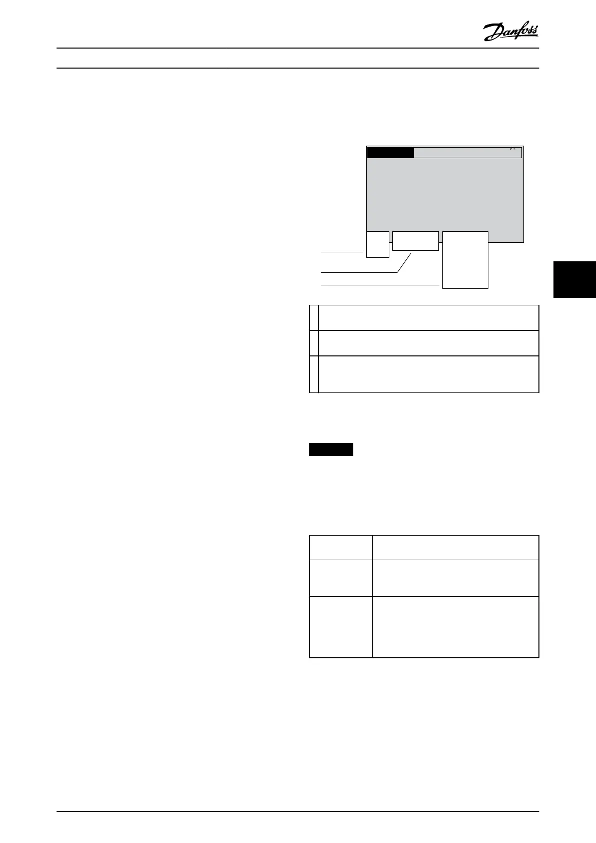
Status Messages
When the drive system is in status mode, status messages
are generated automatically and appear in the bottom line
of the LCP display (see Illustration 6.1.) Status messages are
dened in Table 6.1 to Table 6.3.
Status
799RPM 7.83A 36.4kW
0.000
53.2%
1(1)
Auto
Hand
O
Remote
Local
Ramping
Stop
Running
Jogging
.
.
.
Stand-by
130BB037.11
1
2
3
1
The 1
st
part of the status line indicates where the stop/start
command originates. See Table 6.1.
2
The 2
nd
part of the status line indicates where the speed
control originates. See Table 6.2.
3 The last part of the status line gives the present status of the
drive system. The status shows the operational mode of the
drive system. See Table 6.3.
Illustration 6.1 Status Display
NOTICE
In auto/remote mode, the drive system requires external
commands to execute functions.
Table 6.1 to Table 6.3 dene the meaning of the displayed
status messages.
O The drive system does not react to any control
signal until [Auto On] or [Hand On] is pressed.
Auto The start/stop commands are sent via the
control terminals and/or the serial communi-
cation.
Hand The navigation keys on the LCP can be used
to control the drive system. Stop commands,
reset, reversing, DC brake, and other signals
applied to the control terminals can override
local control.
Table 6.1 Operating Mode
Maintenance, Diagnostics, a... User Guide
MG37L202 Danfoss A/S © 08/2017 All rights reserved. 31
6
6

 Loading...


