1.
2.
3.2 Installing STO
For motor connection, AC mains connection, and control wiring, follow the instructions for safe installation in the Operating Guide
of the drive. See 2.5 Safety Precautions and the relevant drive. For installation with the Ex-certified VLT® PTC Thermistor Card MCB
112, see 3.3 Installation in Combination with VLT® PTC Thermistor Card MCB 112.
Procedure
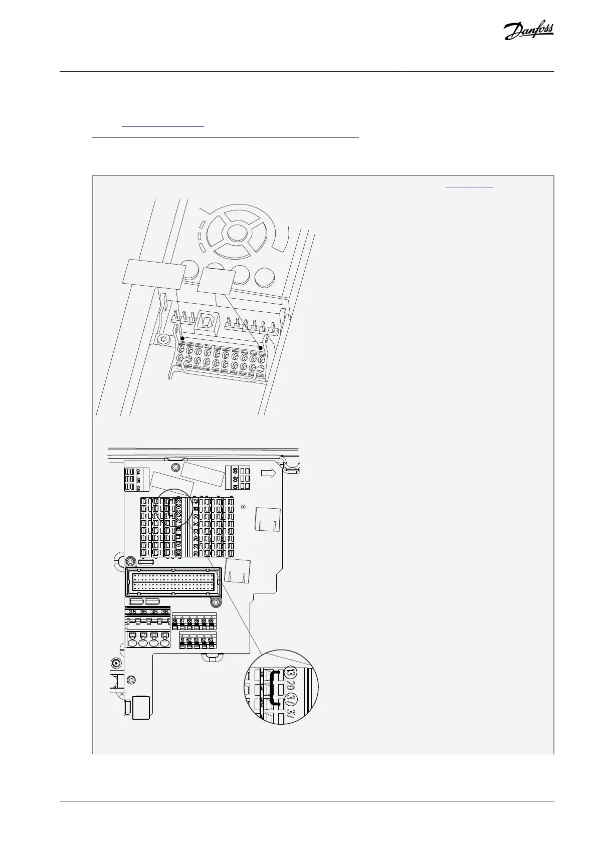
Remove the yellow jumper wire between control terminals 37 and 12 or 13.
Cutting or breaking the yellow jumper is not sufficient to avoid short-circuiting, see jumper in Illustration 1.
Illustration 1: Jumper between Terminals 12/13 (24 V) and 37 (all Drives Except FCD 302)
Illustration 2: Jumper between Terminals 13 (24 V) and 37 (FCD 302)
For example, connect an external safety monitoring relay via an NO safety function to terminal 37 (STO) and either terminal
12 or 13 (24 V DC).
AQ313340186453en-00101 / 130R0544 | 11Danfoss A/S © 2021.03
Installation
Safe Torque Off
Operating Guide

 Loading...


