3.
•
•
•
Connection and application examples are found in the chapter Application Examples.
Complete wiring according to the instructions given in the Operating Guide of the drive.
3.3 Installation in Combination with VLT® PTC Thermistor Card MCB 112
N O T I C E
The combination of VLT® PTC Thermistor Card MCB 112 and STO function is only available for VLT® HVAC Drive FC 102, VLT®
Refrigeration Drive FC 103, VLT® AQUA Drive FC 202, VLT® AutomationDrive FC 302, and VLT® AutomationDrive FC 301 enclosure
size A1.
VLT® PTC Thermistor Card MCB 112 uses terminal 37 as its safety-related switch-off channel.
Ensure that the output X44/12 of MCB 112 is AND-ed with the safety-related sensor (for example, emergency stop button and
safeguard switch) that activates STO. This means that the output to STO terminal 37 is high (24 V) only if both the signal from
MCB 112 output X44/12 and the signal from the safety-related sensor are high. If at least 1 of the 2 signals is low, the output to
terminal 37 must be low too.
Ensure that the safety device with AND-logic complies with the needed safety level.
Short-circuit protect the connection from the output of the safety device with safe AND-logic to the STO terminal 37.
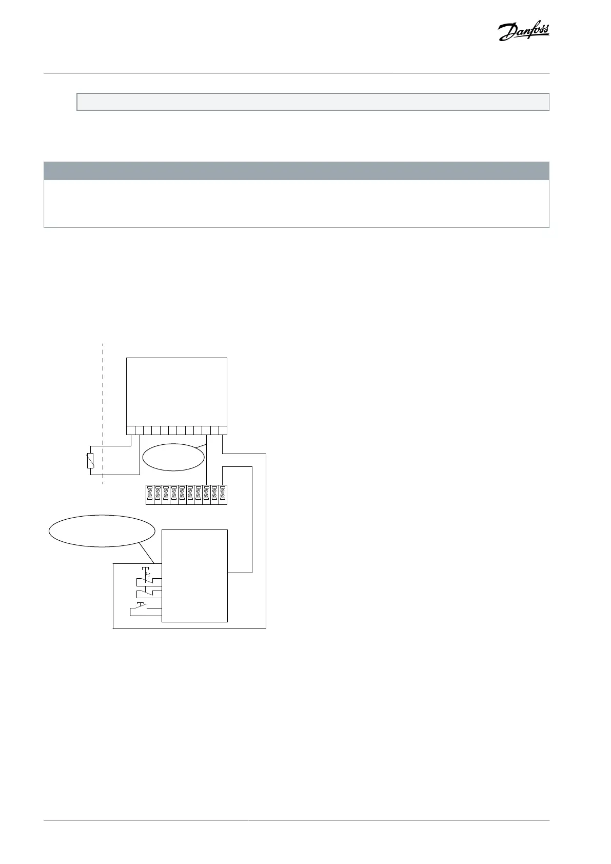
X44/
PTC Thermistor Card
MCB 112
1 2 3 4 5 6 7 8 9 101112
Safety device
Manual restart
SIL 2
Safe AND input
Safe output
Safe input
DI DI
STO
12 13 18 19 27 29 32 33 20 37
e.g. Par 5-15
Illustration 3: Combination of an STO Application and an MCB 112 Application
The illustration shows a restart input for the external safety device. This means that in this installation, parameter 5-19 Terminal 37
Safe Stop can be set to value [7] PTC 1 & Relay W or [8] PTC 1 & Relay A/W. Refer to VLT® PTC Thermistor Card MCB 112 Operating
Guide for further details.
AQ313340186453en-00101 / 130R054412 | Danfoss A/S © 2021.03
Installation
Safe Torque Off
Operating Guide

 Loading...


