•
•
•
•
e30bg776.11
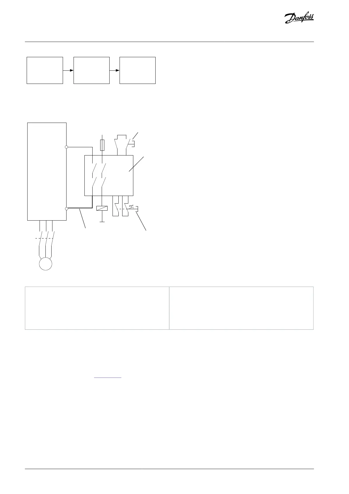
SB emergency
stop device
SB FC 300 safe stop
(terminal 37)
from Danfoss
VLT library
SB safety relay
Illustration 7: Safety-related Block Diagram
5.4 Emergency Stop of Drive with STO, Safety Relay, and Output Contactor - Category 4, PL e, SIL3
Illustration 8: Drive with STO, Safety Relay, and Output Contactor, Category 4, PL e, SIL3
Safety relay (Category 4, PL e, SIL 3)
Short-circuit protected cable (if not inside installa-
tion IP54 cabinet). See ISO 13849-2, Table D.4 for fur-
ther information.
Safety function
If there is an emergency, the emergency stop device is activated. The STO function in the drive is activated. Following a stop or
emergency stop command, the drive is halted.
Where the safety control system must be in accordance with PL e ISO 13849-1 or SIL3 (EN 62061 and IEC 61508), it requires a 2-
channel stop for the STO function. One channel can be implemented by the STO input on the drive and the other by a contactor,
which may be connected in either the drive input or output power circuits. The contactor must be monitored through an auxiliary-
guided contact, shown as K1 in
Illustration 8.
Design features
The circuit can be used up to category 4 and PL e.
For PL e, the complete safety functions have to be calculated (MTTFd).
Use basic safety principles.
Device used for activation of STO and safety relay must be suitable for the selected category, PL or SIL.
When implementing the emergency stop, pay attention to the following tips:
AQ313340186453en-00101 / 130R054418 | Danfoss A/S © 2021.03
Application Examples
Safe Torque Off
Operating Guide

 Loading...


