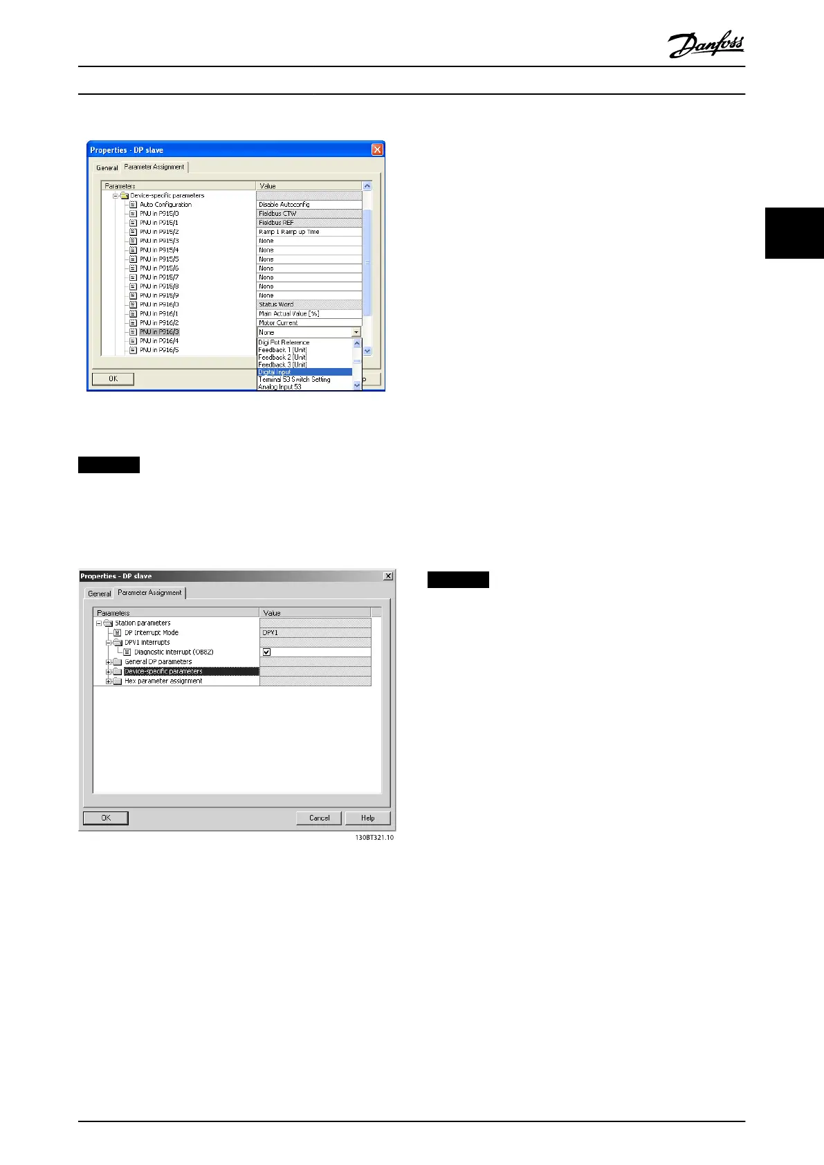
Illustration 3.9 Enable Feature under DP Follower Properties
NOTICE
DP V1 diagnosis is supported for PROFIBUS SW version
2.x and higher. The default setting of the PROFIBUS
option is DP V1 diagnosis. If DP V0 diagnosis is required,
change the setting under DP follower Properties.
Illustration 3.10 DP V1 Diagnosis
Download the configuration file to the PLC. The PROFIBUS
system is able to go online, and it starts to exchange data
when the PLC is set to Run mode.
3.3
Configure the Frequency Converter
3.3.1 Frequency Converter Parameters
The following parameters are important when configuring
the frequency converter with a PROFIBUS interface:
•
0-40 [Hand on] Key on LCP. Pressing [Hand on]
disables control of the frequency converter via
PROFIBUS.
•
Parameter 8-02 Control Word Source. After an
initial power-up, the frequency converter
automatically detects whether a fieldbus option is
installed in slot A, and sets parameter 8-02 Control
Word Source to [Option A]. If an option is added
or changed in or removed from an already
commissioned frequency converter, it does not
change parameter 8-02 Control Word Source, but
enters Trip mode, and the frequency converter
displays an error.
•
Parameter 8-10 Control Word Profile. Select
between the Danfoss FC Profile and the
PROFIdrive profile.
•
8-50 Coasting Select to 8-56 Preset Reference Select.
Select how to gate PROFIBUS control commands
with digital input command of the control card.
•
Parameter 8-03 Control Word Timeout Time to
8-05 End-of-Timeout Function. Set the reaction in
the event of a bus time-out via these parameters.
•
9-18 Node Address.
•
Parameter 8-07 Diagnosis Trigger.
NOTICE
When 8-01 Control Site is set to , the settings in
8-50 Coasting Select to 8-56 Preset Reference Select are
overruled, and all act on Bus-control.
3.3.2 LEDs
The 2 bi-colour LEDs in the PROFIBUS card indicate the
status of PROFIBUS communication.
The LED marked NS (FCD 302: NS2) indicates the network
status, that is, the cyclical communication to the PROFIBUS
master. When this light is constant green, data exchange
between the master and the frequency converter is active.
The LED marked MS (FCD 302: BUS MS) indicates the
module status, that is, acyclical DP V1 communication from
either a PROFIBUS master class 1 (PLC) or a master class 2
(MCT 10, FDT tool). When this light is constant green, DP
V1 communication from master classes 1 and 2 is active.
For details of the full range of communications status
indicated by the LEDs, refer to chapter 8 Troubleshooting.
Configuration
Programming Guide
MG37G102 Danfoss A/S © Rev. 05/2014 All rights reserved. 11
3 3

 Loading...


