•
MRV represents the process setpoint.
•
MAV expresses the actual process feedback
(range ±200%).
4.2.5 Influence of the Digital Input
Terminals upon FC Control Mode
Set the influence of the digital input terminals upon
control of the frequency converter in 8-50 Coasting Select
to 8-56 Preset Reference Select.
NOTICE
The setting of 8-01 Control Site overrules the settings in
8-50 Coasting Select to 8-56 Preset Reference Select. The
setting of terminal 37 Coast stop (safe) overrules any
other parameter.
Each of the digital input signals can be programmed to
logic AND, logic OR, or to have no relation to the
corresponding bit in the control word. In this way the
following signal sources initiate a specific control
command, for example stop/coast:
•
fieldbus only,
•
fieldbus AND digital input, or
•
either fieldbus OR digital input terminal.
CAUTION
To control the frequency converter via PROFIBUS, set
8-50 Coasting Select to either [1] Bus , or to [2] Logic AND,
and set 8-01 Control Site to [0] or [2].
For more detailed information and examples of logical
relationship options, see chapter 8 Troubleshooting.
4.3
Control Profile
Control the frequency converter according to
•
the PROFIdrive profile, see chapter 4.4 PROFIdrive
Control Profile, or
•
the Danfoss FC control profile, see
chapter 4.5 Danfoss FC Control Profile.
Select the desired control profile in parameter 8-10 Control
Word Profile. The choice of profile affects the control and
status word only.
Chapter 4.4 PROFIdrive Control Profile and
chapter 4.5 Danfoss FC Control Profile provide a detailed
description of control and status data.
4.4
PROFIdrive Control Profile
This section describes the functionality of the control word
and status word in the PROFIdrive profile.
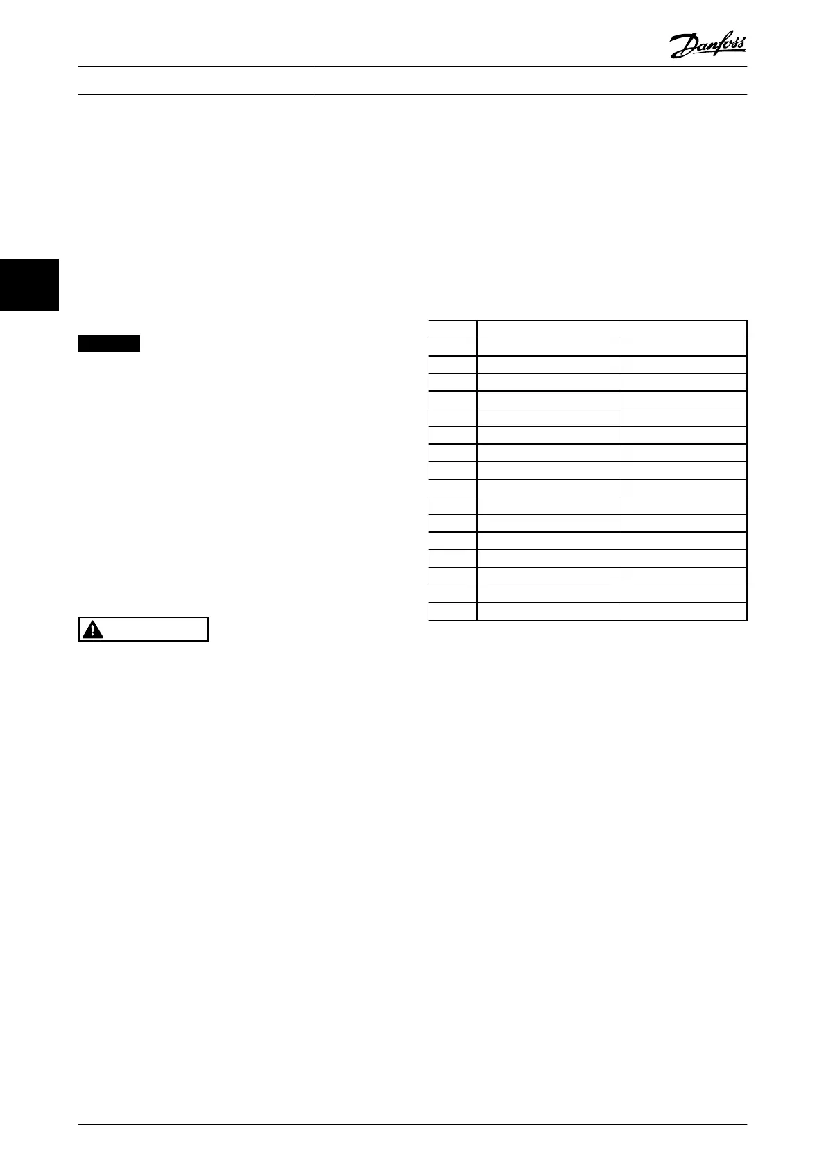
4.4.1 Control Word according to PROFIdrive
Profile (CTW)
The control word is used to send commands from a master
(e.g. a PC) to a follower.
Bit Bit=0 Bit=1
00 OFF 1 ON 1
01 OFF 2 ON 2
02 OFF 3 ON 3
03 Coasting No coasting
04 Quick stop Ramp
05 Hold frequency output Use ramp
06 Ramp stop Start
07 No function Reset
08 Jog 1 OFF Jog 1 ON
09 Jog 2 OFF Jog 2 ON
10 Data invalid Data valid
11 No function Slow down
12 No function Catch up
13 Parameter set-up Selection lsb
14 Parameter set-up Selection msb
15 No function Reverse
Table 4.5 Control Word Bits
Explanation of the control bits
Bit 00, OFF 1/ON 1
Normal ramp stops using the ramp times of the actual
selected ramp.
Bit 00="0" leads to the stop and activation of the output
relay 1 or 2 if the output frequency is 0 Hz and if [Relay
123] has been selected in 5-40 Function Relay.
When bit 0="1", the frequency converter is in State 1:
“Switching on inhibited”.
Refer to Illustration 4.4.
Bit 01, OFF 2/ON 2
Coasting stop.
When bit 01="0", a coasting stop and activation of the
output relay 1 or 2 occurs if the output frequency is 0 Hz
and if [Relay 123] has been selected in 5-40 Function Relay.
When bit 01="1", the frequency converter is in State 1:
“Switching on inhibited”. Refer to Illustration 4.4.
Bit 02, OFF 3/ON 3
Quick stop using the ramp time of 3-81 Quick Stop Ramp
Time.
When bit 02="0", a quick stop and activation of the output
relay 1 or 2 occurs if the output frequency is 0 Hz and if
[Relay 123] has been selected in 5-40 Function Relay.
When bit 02="1", the frequency converter is in State 1:
“Switching on inhibited”.
Control
Programming Guide
16 Danfoss A/S © Rev. 05/2014 All rights reserved. MG37G102
44

 Loading...


