Bit Bit value=0 Bit value=1 Bit value
00 Control not ready Control ready 1
7
01 Drive not ready Drive ready 1
02 Coasting Enable 1
03 No error Trip 0
04 No error Error (no trip) 0
0
05 Reserved - 0
06 No error Triplock 0
07 No warning Warning 0
08 Speed reference Speed = reference 1
F
09 Local operation Bus control 1
10 Outside frequency range Within frequency range 1
11 No operation In operation 1
12 Drive OK Stopped, autostart 0
0
13 Voltage OK Voltage exceeded 0
14 Torque OK Torque exceeded 0
15 Timers OK Timers exceeded 0
Function active
Function inactive
Table 7.6 Active Bit Functions for Status Word Telegram using PPO Type
7.4 Example 4: PLC Programming
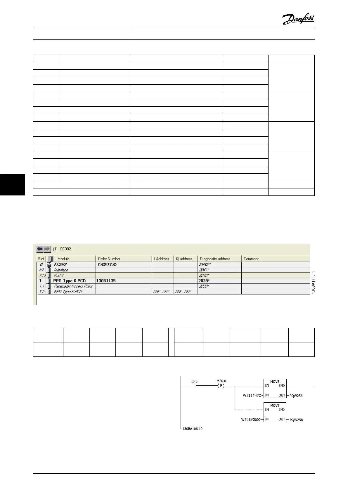
In this example PPO type 6 is placed in the input/output address, see Illustration 7.2 and Table 7.7.
Illustration 7.2 FC 302 and PPO Type 6 PCD
Input
address
256-257 258-259 260-261 262-263 Output
address
256-257 258-259 260-261 262-263
Set-up Status
word
MAV Motor
torque
Digital
input
Set-up Control
word
Reference Not used Not used
Table 7.7 Input/Output Address Set-up
This network sends a start command (047C hex) and a
reference (2000 hex) of 50% to the frequency converter.
Illustration 7.3 Network Sends a Start Command and a
Reference of 50% to the Frequency Converter.
Application Examples
Programming Guide
46 Danfoss A/S © Rev. 05/2014 All rights reserved. MG37G102
77

 Loading...


