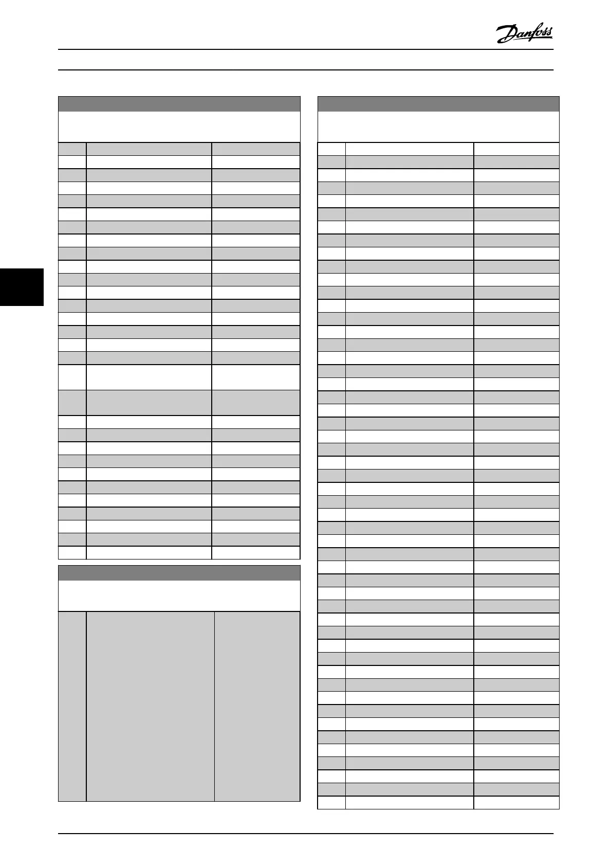
9-15 PCD Write Configuration
Array [10]
Option: Function:
[342] Ramp 1 Ramp Down Time
[351] Ramp 2 Ramp Up Time
[352] Ramp 2 Ramp Down Time
[380] Jog Ramp Time
[381] Quick Stop Ramp Time
[411] Motor Speed Low Limit [RPM]
[412] Motor Speed Low Limit [Hz]
[413] Motor Speed High Limit [RPM]
[414] Motor Speed High Limit [Hz]
[416] Torque Limit Motor Mode
[417] Torque Limit Generator Mode
[553] Term. 29 High Ref./Feedb. Value
[558] Term. 33 High Ref./Feedb. Value
[590] Digital & Relay Bus Control
[593] Pulse Out #27 Bus Control
[595] Pulse Out #29 Bus Control
[597] Pulse Out #X30/6 Bus Control
[615] Terminal 53 High Ref./Feedb.
Value
[625] Terminal 54 High Ref./Feedb.
Value
[653] Term 42 Output Bus Ctrl
[663] Terminal X30/8 Bus Control
[673] Terminal X45/1 Bus Control
[683] Terminal X45/3 Bus Control
[748] PCD Feed Forward
[890] Bus Jog 1 Speed
[891] Bus Jog 2 Speed
[1680] Fieldbus CTW 1
[1682] Fieldbus REF 1
[1685] FC Port CTW 1
[1686] FC Port REF 1
9-16 PCD Read Configuration
[10] Array
Option: Function:
Select the parameters
to be assigned to
PCD 3 to 10 of the
telegrams. The
number of available
PCDs depends on the
telegram type. PCDs 3
to 10 contain the
actual data values of
the selected
parameters. For
standard PROFIBUS
telegrams, see
9-22 Telegram
Selection.
9-16 PCD Read Configuration
[10] Array
Option: Function:
[0] None
[15] Readout: actual setup
[1472] Legacy Alarm Word
[1473] Legacy Warning Word
[1474] Leg. Ext. Status Word
[1500] Operating hours
[1501] Running Hours
[1502] kWh Counter
[1600] Control Word
[1601] Reference [Unit]
[1602] Reference %
[1603] Status Word
[1605] Main Actual Value [%]
[1609] Custom Readout
[1610] Power [kW]
[1611] Power [hp]
[1612] Motor Voltage
[1613] Frequency
[1614] Motor current
[1615] Frequency [%]
[1616] Torque [Nm]
[1617] Speed [RPM]
[1618] Motor Thermal
[1619] KTY sensor temperature
[1620] Motor Angle
[1621] Torque [%] High Res.
[1622] Torque [%]
[1623] Motor Shaft Power [kW]
[1624] Calibrated Stator Resistance
[1625] Torque [Nm] High
[1630] DC Link Voltage
[1632] Brake Energy /s
[1633] Brake Energy /2 min
[1634] Heatsink Temp.
[1635] Inverter Thermal
[1638] SL Controller State
[1639] Control Card Temp.
[1645] Motor Phase U Current
[1646] Motor Phase V Current
[1647] Motor Phase W Current
[1648] Speed Ref. After Ramp [RPM]
[1650] External Reference
[1651] Pulse Reference
[1652] Feedback[Unit]
[1653] Digi Pot Reference
[1657] Feedback [RPM]
[1660] Digital Input
[1661] Terminal 53 Switch Setting
[1662] Analog Input 53
[1663] Terminal 54 Switch Setting
[1664] Analog Input 54
Parameters Programming Guide
36 Danfoss A/S © Rev. 05/2014 All rights reserved. MG37G102
66

 Loading...


