3.4 Main Menu–Reference/Ramps–Group 3
3.4.1 3-0* Reference Limits
Parameters for setting the reference unit, limits, and
ranges.
Also see parameter group 20-0* Feedback for information on
settings in closed loop.
3-02 Minimum Reference
Range: Function:
0* [-4999–4999] The minimum reference is the lowest value
obtainable by summing all references.
3-03 Maximum Reference
Range: Function:
Size
related*
[ -4999.0 - 4999
ReferenceFeed-
backUnit]
The maximum reference is the
highest value obtainable by
summing all references. The
maximum reference unit matches
the selection of conguration in
parameter 1-00 Conguration
Mode.
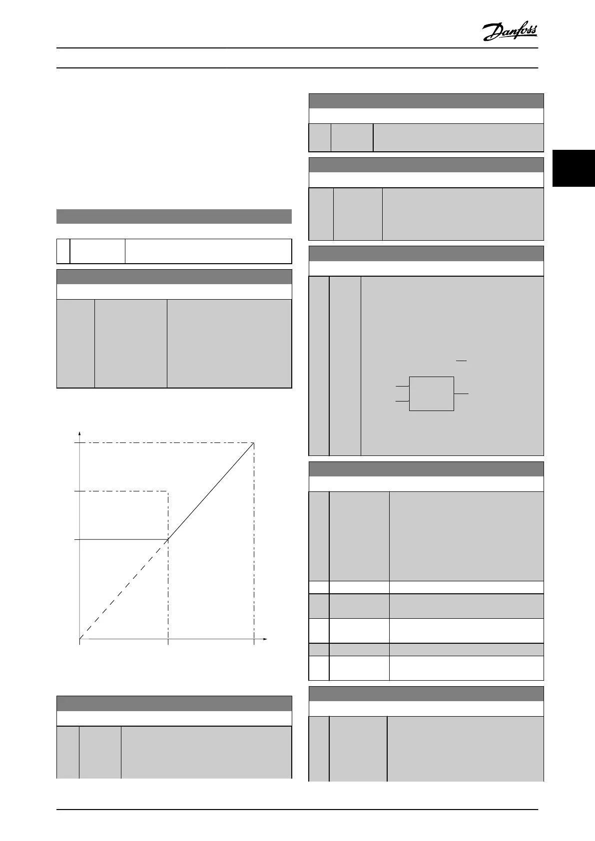
3.4.2 3-1* References
P3-03
P3-02
0 50 100%
P3-10
130BB036.10
Illustration 3.4 References
3-10 Preset Reference
Range: Function:
0 %* [-100 -
100 %]
Enter up to 8 dierent preset references (0–7)
in this parameter, using array programming. For
selecting dedicated references, select preset
reference bit 0/1/2 [16], [17], or [18] for the
3-10 Preset Reference
Range: Function:
corresponding digital inputs in parameter group
5-1* Digital Inputs.
3-11 Jog Speed [Hz]
Range: Function:
5 Hz* [ 0 - 500.0
Hz]
The jog speed is a xed output speed at
which the frequency converter runs when
the jog function is activated.
See also parameter 3-80 Jog Ramp Time.
3-14 Preset Relative Reference
Range: Function:
0 %
*
[-100
-
100 %]
Dene the xed value in % to be added to the
variable value dened in parameter 3-18 Relative
Scaling Reference Resource.
The sum of xed and variable values (labeled Y in
Illustration 3.5) is multiplied by actual reference
(labeled X in Illustration 3.5). This product is added
to actual reference X + X ×
Y
100
Relative
Z=X+X*Y/100
Resulting
actual
reference
Y
X
130BA059.12
Z
Illustration 3.5 Preset Relative Reference
3-15 Reference 1 Source
Option: Function:
Select the input to be used for the 1
st
reference signal. Parameter 3-15 Reference 1
Source, parameter 3-16 Reference 2 Source,
and parameter 3-17 Reference 3 Source
dene up to 3 dierent reference signals.
The sum of these reference signals denes
the actual reference.
[0] No function
[1] * Analog Input
53
[2] Analog Input
54
[7] Pulse input 29
[11] Local bus
reference
3-16 Reference 2 Source
Option: Function:
Select the input to be used for the 2
nd
reference signal. Parameter 3-15 Reference 1
Source, parameter 3-16 Reference 2 Source,
and parameter 3-17 Reference 3 Source
dene up to 3 dierent reference signals.
Parameters Programming Guide
MG18B502 Danfoss A/S © 04/2018 All rights reserved. 41
3 3

 Loading...


