3.9 Main Menu - Smart Logic - Group 13
3.9.1 13-** Prog. Features
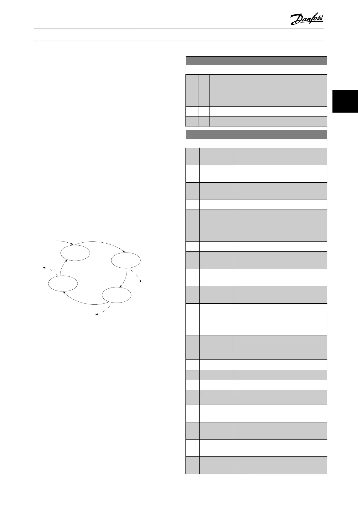
Smart logic control (SLC) is a sequence of user-dened
actions (see parameter 13-52 SL Controller Action [x])
executed by the SLC when the SLC evaluates the
associated user-dened event (see parameter 13-51 SL
Controller Event [x]) as true. Events and actions are each
numbered and linked in pairs. This means that when [0]
event is fullled (attains the value true), [0] action is
executed. After executing this action, the conditions of [1]
event is evaluated. If it is evaluated as true, [1] action is
executed, and so on. Only 1 event is evaluated at any time.
If an event is evaluated as false, nothing happens (in the
SLC) during the current scan interval and no other events
are evaluated. This means that when the SLC starts, it
evaluates [0] event (and only [0] event) each scan interval.
Only when [0] event is evaluated as true, the SLC executes
[0] action and starts evaluating [1] event. It is possible to
program from 1–20 events and actions. When the last
event/action has been executed, the sequence starts over
again from [0] event/[0] action.
130BA062.14
State 1
13-51.0
13-52.0
State 2
13-51.1
13-52.1
Start
event P13-01
State 3
13-51.2
13-52.2
State 4
13-51.3
13-52.3
Stop
event P13-02
Stop
event P13-02
Stop
event P13-02
Illustration 3.13 Example with 3 Event/Actions
Starting and stopping the SLC
To start or stop the SLC, select [1] On or [2] O in
parameter 13-00 SL Controller Mode. The SLC always starts
in state 0 (where it evaluates [0] event). The SLC starts
when the start event (dened in parameter 13-01 Start
Event) is evaluated as true (if [1] On is selected in
parameter 13-00 SL Controller Mode). The SLC stops when
the stop event (parameter 13-02 Stop Event) is true.
Parameter 13-03 Reset SLC resets all SLC parameters and
starts programming from the beginning.
3.9.2 13-0* SLC Settings
To activate, deactivate, and reset the smart logic control
sequence, use the SLC settings. The logic functions and
comparators are always running in the background, which
opens for separate control of digital inputs and outputs.
13-00 SL Controller Mode
Option: Function:
To enable the smart logic control to start when a start
command is present, for example, via a digital input,
Select [1] On. To disable the smart logic control, select
[0] O.
[0] * O Disables the smart logic controller.
[1] On Enables the smart logic controller.
13-01 Start Event
Option: Function:
To activate smart logic control, select the
boolean (true or false) input.
[0] False Enters the xed value of false in the logic
rule.
[1] True Enters the xed value of true in the logic
rule.
[2] Running The motor runs.
[3] In range The motor runs within programmed
current ranges (parameter 4-50 Warning
Current Low and parameter 4-51 Warning
Current High).
[4] On reference The motor runs at reference speed.
[7] Out of current
range
The motor current is outside the range set
in parameter 4-18 Current Limit.
[8] Below I low The motor current is lower than set in
parameter 4-50 Warning Current Low.
[9] Above I high The motor current is higher than set in
parameter 4-51 Warning Current High.
[16] Thermal
warning
The thermal warning turns on when the
temperature exceeds the limit in the
motor, the frequency converter, or the
thermistor.
[17] Mains out of
range
Mains phase loss warning or alarm, if
parameter 14-12 Function at Mains
Imbalance is not set at [2] Disabled.
[18] Reversing The frequency converter reverses.
[19] Warning A warning is present.
[20] Alarm (trip) An alarm is present.
[21] Alarm (trip
lock)
A trip lock alarm is present.
[22] Comparator 0 Use the result of comparator 0 in the logic
rule.
[23] Comparator 1 Use the result of comparator 1 in the logic
rule.
[24] Comparator 2 Use the result of comparator 2 in the logic
rule.
[25] Comparator 3 Use the result of comparator 3 in the logic
rule.
Parameters Programming Guide
MG18B502 Danfoss A/S © 04/2018 All rights reserved. 67
3 3

 Loading...


