4 Troubleshooting
4.1 Introduction to Alarms and Warnings
A warning or alarm is signaled by the relevant indicator
light on the front of the frequency converter and indicated
by a code on the display.
A warning remains active until its cause is no longer
present. Under certain circumstances, operation of the
motor may still continue. Warning messages may be
critical, but are not necessarily so.
If an alarm occurs, the frequency converter has tripped.
Alarms must be reset to restart operation once their cause
has been rectied.
This may be done in 4 ways:
1. By pressing [Reset].
2. Via a digital input with the Reset function.
3. Via serial communication.
4. By resetting automatically using the [Auto Reset]
function, see parameter 14-20 Reset Mode.
NOTICE
After a manual reset pressing [Reset], press [Auto On] or
[Hand On] to restart the motor.
If an alarm cannot be reset, the reason may be that its
cause has not been rectied, or the alarm is trip-locked,
see Table 4.1.
Alarms that are trip-locked oer extra protection. This
means that the mains supply must be switched o before
the alarm can be reset. After being switched back on, the
frequency converter is no longer blocked and may be reset
as described above once the cause has been rectied.
Alarms that are not trip-locked can also be reset using the
automatic reset function in parameter 14-20 Reset Mode
(Warning: automatic wake-up is possible.)
If a warning and alarm are marked against a code in
Table 4.1, this means that either a warning occurs before
an alarm, or it can be specied if a warning or an alarm
should be displayed for a given fault.
This is possible, for instance, in parameter 1-90 Motor
Thermal Protection. After an alarm or trip, the motor carries
on coasting, and the alarm and warning ash on the
frequency converter. Once the problem has been rectied,
only the alarm continues ashing.
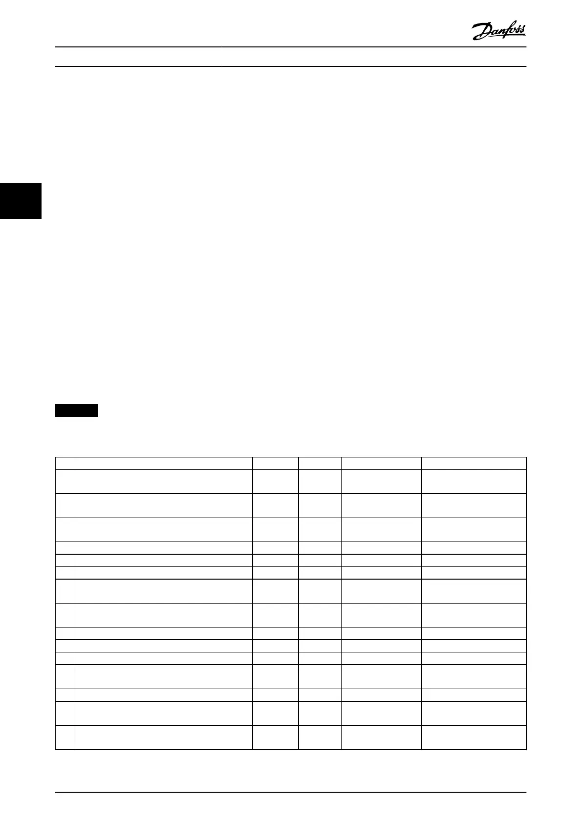
No. Description Warning Alarm Trip Lock Parameter Reference
2 Live zero error (X) (X) – Parameter 6-01 Live Zero
Timeout Function
3 No motor (X) – – Parameter 1-80 Function at
Stop
4 Mains phase loss (X) (X) (X) Parameter 14-12 Function at
Mains Imbalance
7 DC over voltage X X – –
8 DC under voltage X X – –
9 Inverter overloaded X X – –
10 Motor ETR overtemperature (X) (X) – Parameter 1-90 Motor Thermal
Protection
11 Motor thermistor overtemperature (X) (X) – Parameter 1-90 Motor Thermal
Protection
13 Overcurrent X X X –
14 Ground fault X X X –
16 Short circuit – X X –
17 Control word time-out (X) (X) – Parameter 8-04 Control
Timeout Function
24 Fan fault (Only on 400 V 30–90kW) X X – Parameter 14-53 Fan Monitor
30 Motor phase U missing – (X) (X) Parameter 4-58 Missing Motor
Phase Function
31 Motor phase V missing – (X) (X) Parameter 4-58 Missing Motor
Phase Function
Troubleshooting
VLT
®
HVAC Basic Drive FC 101
98 Danfoss A/S © 04/2018 All rights reserved. MG18B502
44

 Loading...


