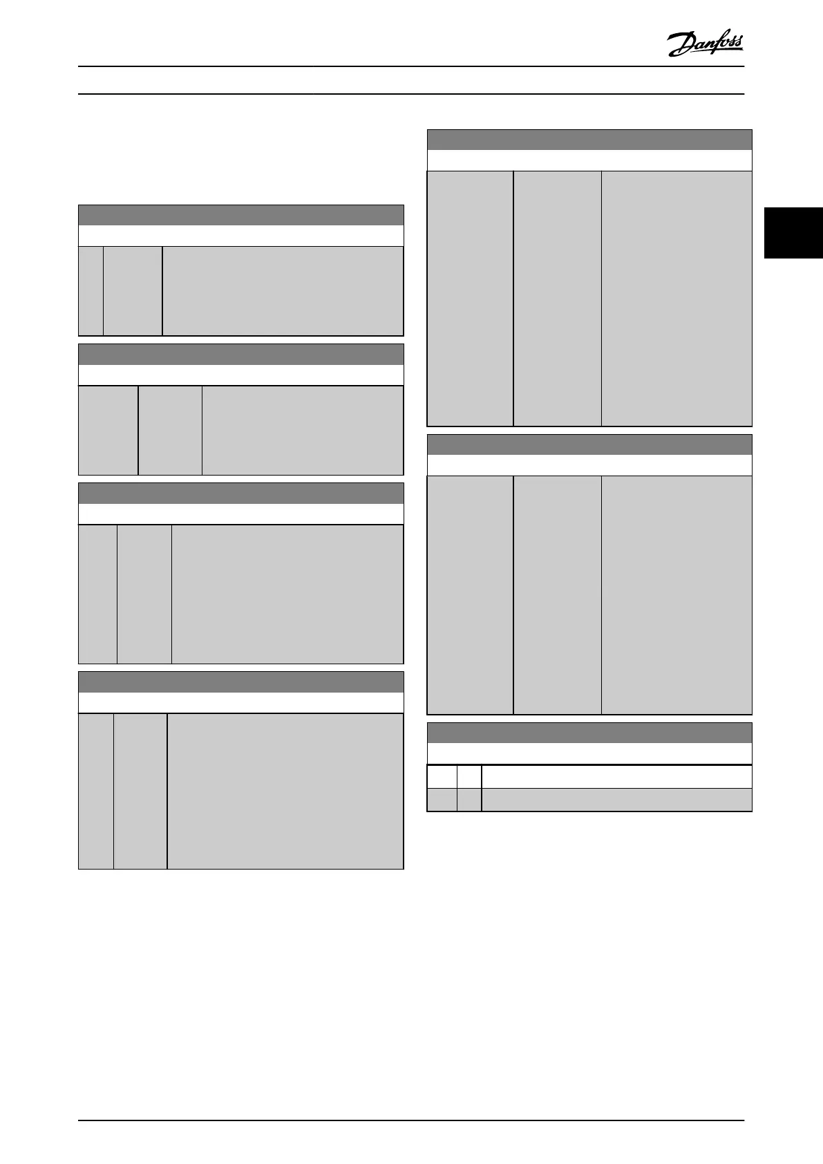
3.5.3 4-5* Adj. Warnings
Dene adjustable warning limits for current. Warnings are
shown on the display, programmed output, or eldbus.
4-50 Warning Current Low
Range: Function:
0 A [ 0 - 500
A]
Enter the I
LOW
value. When the motor current
drops below this limit, a bit in the status word is
set. This value can also be programmed to
produce a signal on the digital output or the
relay output.
4-51 Warning Current High
Range: Function:
Size
related*
[ 0.0 -
500.00 A]
Enter the I
HIGH
value. When the motor
current exceeds this limit, a bit in the
status word is set. This value can also
be programmed to produce a signal on
the digital output or the relay output.
4-54 Warning Reference Low
Range: Function:
-4999* [-4999 -
4999 ]
Enter the lower reference limit. When the
actual reference drops below this limit, the
display indicates Ref
Low
. Warning bit 20 is set
in parameter 16-94 Ext. Status Word. The
output relay or the digital output can be
congured to indicate this warning. The LCP
warning indicator light is not turned on when
this parameter set limit is reached.
4-55 Warning Reference High
Range: Function:
4999* [-4999 -
4999 ]
Use this parameter to set a higher limit for the
reference range.
When the actual reference exceeds this limit,
the display reads Reference High. Warning bit
19 is set in parameter 16-94 Ext. Status Word.
The output relay or the digital output can be
congured to indicate this warning. The LCP
warning indicator light is not turned on when
this parameter set limit is reached.
4-56 Warning Feedback Low
Range: Function:
-4999
ProcessCtrlUnit*
[-4999 - 4999
ProcessCtrlUnit]
Use this parameter to set a
lower limit for the feedback
range.
When the feedback drops
below this limit, the display
reads Feedback Low. Warning
bit 6 is set in
parameter 16-94 Ext. Status
Word. The output relay or
digital output can be
congured to indicate this
warning. The LCP warning
indicator light is not turned
on when this parameter set
limit is reached.
4-57 Warning Feedback High
Range: Function:
4999
ProcessCtrlUnit*
[-4999 - 4999
ProcessCtrlUnit]
Use this parameter to set a
higher limit for the feedback
range.
When the feedback exceeds
this limit, the display reads
Feedback High. Warning bit 5
is set in parameter 16-94 Ext.
Status Word. The output relay
or digital output can be
congured to indicate this
warning. The LCP warning
indicator light is not turned
on when this parameter set
limit is reached.
4-58 Missing Motor Phase Function
Option: Function:
[0] O No alarm is shown if a missing motor phase occurs.
[1] * On An alarm is shown if a missing motor phase occurs.
Parameters Programming Guide
MG18B502 Danfoss A/S © 04/2018 All rights reserved. 45
3 3

 Loading...


