3.10 Main Menu - Special Functions - Group
14
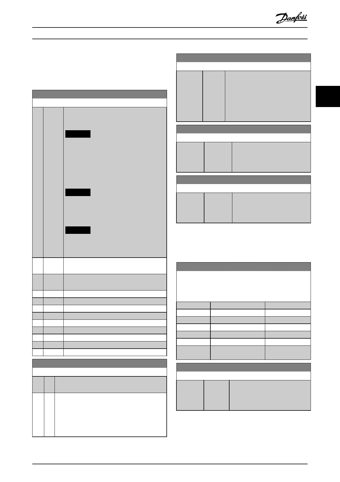
3.10.1 14-0* Inverter Switching
14-01 Switching Frequency
Option: Function:
Select the inverter switching frequency. Changing
the switching frequency can help to reduce
acoustic noise from the motor.
NOTICE
The output frequency value of the
frequency converter must never exceed
1/10 of the switching frequency. When the
motor runs, adjust the switching frequency
in parameter 14-01 Switching Frequency
until the motor is as quiet as possible.
NOTICE
High switching frequencies increase heat
generation in the frequency converter and
may reduce its lifetime.
NOTICE
Not all options are available in all power
sizes.
[0] Ran3 3 kHz true random PWM (white noise
modulation).
[1] Ran5 5 kHz true random PWM (white noise
modulation).
[2] 2.0 kHz
[3] 3.0 kHz
[4] 4.0 kHz
[5] 5.0 kHz
[6] 6.0 kHz
[7] 8.0 kHz
[8] 10.0 kHz
[9] 12.0 kHz
[10] 16.0 kHz
14-03 Overmodulation
Option: Function:
[0] * O Selects no overmodulation of the output voltage to
avoid torque ripple on the motor shaft.
[1] On The overmodulation function generates an extra
voltage of up to 8% of U
max
output voltage without
overmodulation, which results in an extra torque of
10–12% in the middle of the over-synchronous range
(from 0% at nominal speed rising to approximately
12% at double nominal speed).
14-07 Dead Time Compensation Level
Range: Function:
Size
related*
[0 -
100 ]
Level of applied dead time compensation
in percentage. A high level (>90%)
optimizes the dynamic motor response. A
level 50–90% is suitable for both motor-
torque-ripple minimization and motor
dynamics. A 0 level turns o the dead
time compensation.
14-08 Damping Gain Factor
Range: Function:
Size related* [0 -
100 %]
Set the damping factor for DC-link
voltage compensation. See
parameter 14-51 DC-Link Voltage
Compensation.
14-09 Dead Time Bias Current Level
Range: Function:
Size related* [0 - 100 %] To add to the current-sense signal for
dead time compensation for some
motors, set a bias signal (in
percentage).
3.10.2 14-1* Mains On/O
Parameters for conguring mains failure monitoring and
handling.
14-10 Mains Failure
Congure the action of the frequency converter when the mains
voltage is below the mains voltage limit congured in
parameter 14-11 Mains Fault Voltage Level.
Option: Function:
[0] * No function
[1] Ctrl. ramp-down
[3] Coasting
[4] Kinetic back-up
[5] Kinetic back-up, trip
[6] Alarm
[7] Kin. back-up, trip w
recovery
14-11 Mains Fault Voltage Level
Range: Function:
Size
related*
[100 -
800 V]
Use this parameter to dene at which
AC voltage the function selected in
parameter 14-10 Mains Failure should
be activated.
Parameters Programming Guide
MG18B502 Danfoss A/S © 04/2018 All rights reserved. 75
3 3

 Loading...


