3.8.6 8-8* FC Port Diagnostics
These parameters are used for monitoring the bus
communication via the FC port.
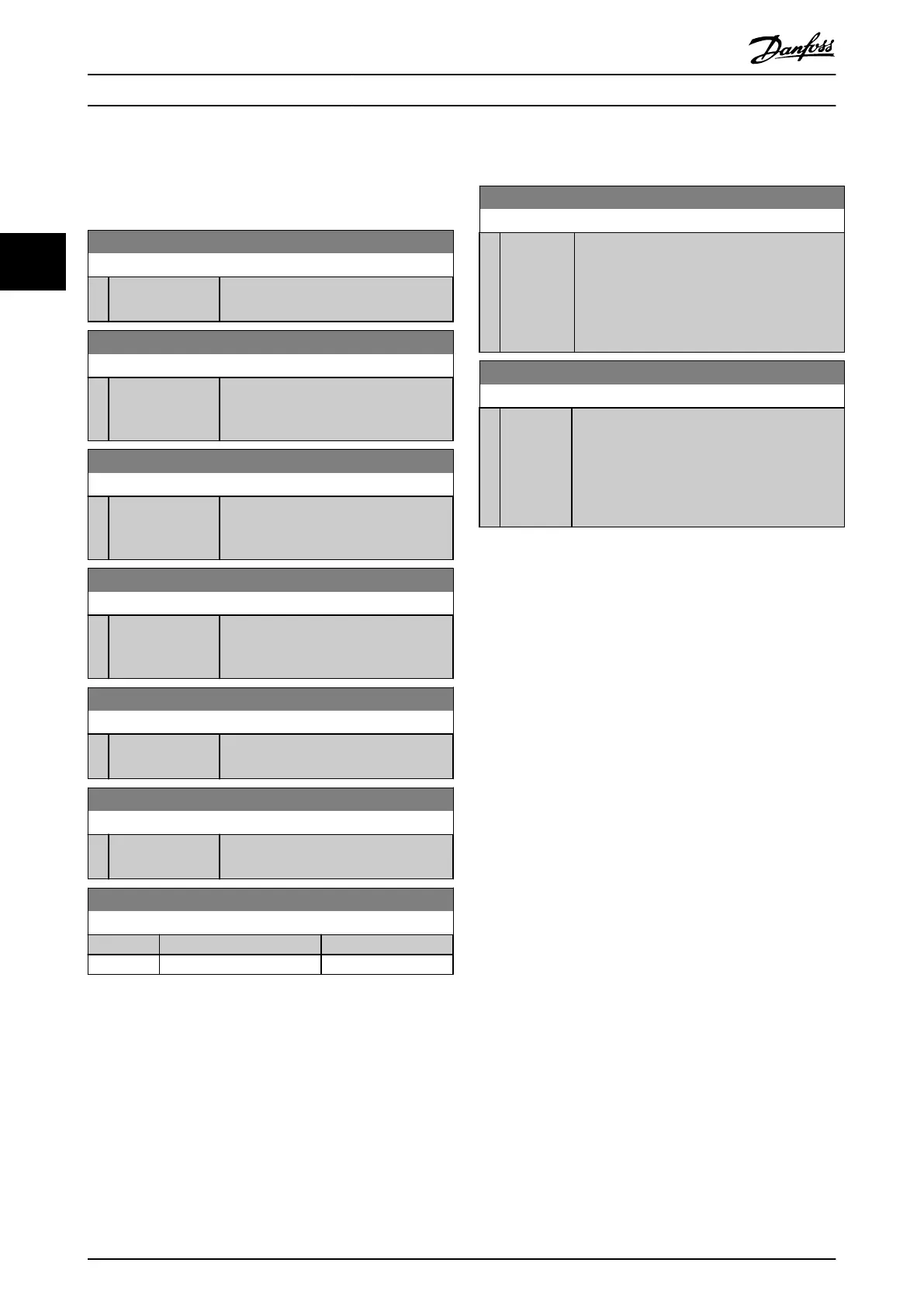
8-80 Bus Message Count
Range: Function:
0* [0 - 4294967295 ] This parameter shows the number of
valid telegrams detected on the bus.
8-81 Bus Error Count
Range: Function:
0* [0 - 4294967295 ] This parameter shows the number of
telegrams with faults (for example, CRC
fault), detected on the bus.
8-82 Slave Messages Rcvd
Range: Function:
0* [0 - 4294967295 ] This parameter shows the number of
valid telegrams addressed to the slave,
sent by the frequency converter.
8-83 Slave Error Count
Range: Function:
0* [0 - 4294967295 ] This parameter shows the number of
error telegrams, which the frequency
converter could not execute.
8-84 Slave Messages Sent
Range: Function:
0* [0 - 4294967295 ] This parameter shows the number of
messages sent from the slave.
8-85 Slave Timeout Errors
Range: Function:
0* [0 - 4294967295 ] This parameter shows the number of
slave timeout errors.
8-88 Reset FC port Diagnostics
Option: Function:
[0] * Do not reset
[1] Reset counter
3.8.7 8-9* Bus Feedback
8-94 Bus Feedback 1
Range: Function:
0* [-32768 -
32767 ]
Write feedback to this parameter via the serial
communication port. Select this parameter in
parameter 20-00 Feedback 1 Source or
parameter 20-03 Feedback 2 Source as a feedback
source. Hex value 4000 h corresponds to 100%
feedback/range is ±200%.
8-95 Bus Feedback 2
Range: Function:
0* [-32768 -
32767 ]
Write a feedback to this parameter via the serial
communication port. This parameter must be
selected in parameter 20-00 Feedback 1 Source or
parameter 20-03 Feedback 2 Source as a feedback
source. The hexadecimal value 4000 h
corresponds to ±200% in 100% feedback/range.
Parameters
VLT
®
HVAC Basic Drive FC 101
66 Danfoss A/S © 04/2018 All rights reserved. MG18B502
33

 Loading...


