5-53 Term. 29 High Ref./Feedb. Value
Range: Function:
Size
related*
[-4999 -
4999 ]
Enter the high reference value [RPM] for
the motor shaft speed and the high
feedback value. Select terminal 29 as a
digital input (parameter 5-13 Terminal 29
Digital Input = applicable value).
3.6.6 5-9* Bus Controlled
This parameter group selects digital and relay outputs via a
eldbus setting.
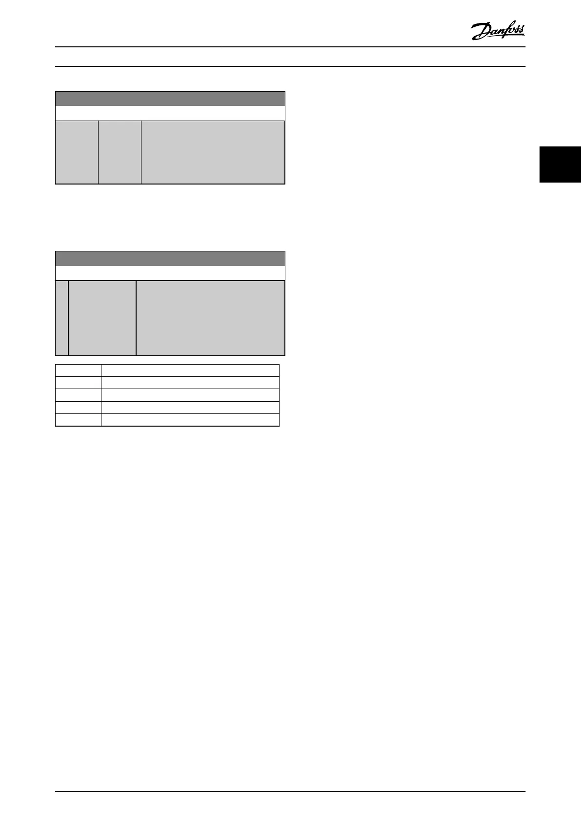
5-90 Digital & Relay Bus Control
Range: Function:
0* [0 - 0xFFFFFFFF ] This parameter holds the state of the bus-
controlled digital outputs and relays.
A logical 1 indicates that the output is
high or active.
A logical 0 indicates that the output is
low or inactive.
Bit 0–3 Reserved
Bit 4 Relay 1 output terminal
Bit 6–23 Reserved
Bit 24 Terminal 42 digital output
Bit 26–31 Reserved
Table 3.5 Bit Functions
Parameters Programming Guide
MG18B502 Danfoss A/S © 04/2018 All rights reserved. 55
3 3

 Loading...


