However, there are exceptions if par. 3-00 is set to
Min - Max
, [0].
Example 1:
Par. 3-02 is set to 20 and par. 3-03 is set to 50. In this case 0% = 0 and 100% = 50.
Example 2:
Par. 3-02 is set to -70 and par. 3-03 is set to 50. In this case 0% = 0 and 100% = 70.
3-11 Jog Speed [Hz]
Range: Function:
Jog speed is a fixed output speed and overrules the selected reference speed, see par. 5-1* selection [14].
If the motor is stopped while in jog mode, the jog signal acts as a start signal.
Removing the jog signal makes the motor run according to the selected configuration.
5.0 Hz [0.0 - 400.0 Hz] Select speed to function as jog speed.
3-12 Catch Up/Slow Down Value
Range: Function:
0%
*
[0 - 100%]
The
Catch-up/Slowdown function
is activated by an input command (see par. 5-1*, choice [28]/[29]). If the
command is active, the Catch-up/Slowdown value (in %) is added to the reference function as follows:
Reference
=
Reference
+
Reference
×
Catchup Slowdown
100
Reference
=
Reference
ì
Reference
×
Catchup Slowdown
100
When the input command is inactivated, the reference returns to its original value ie. Reference = Reference +
0.
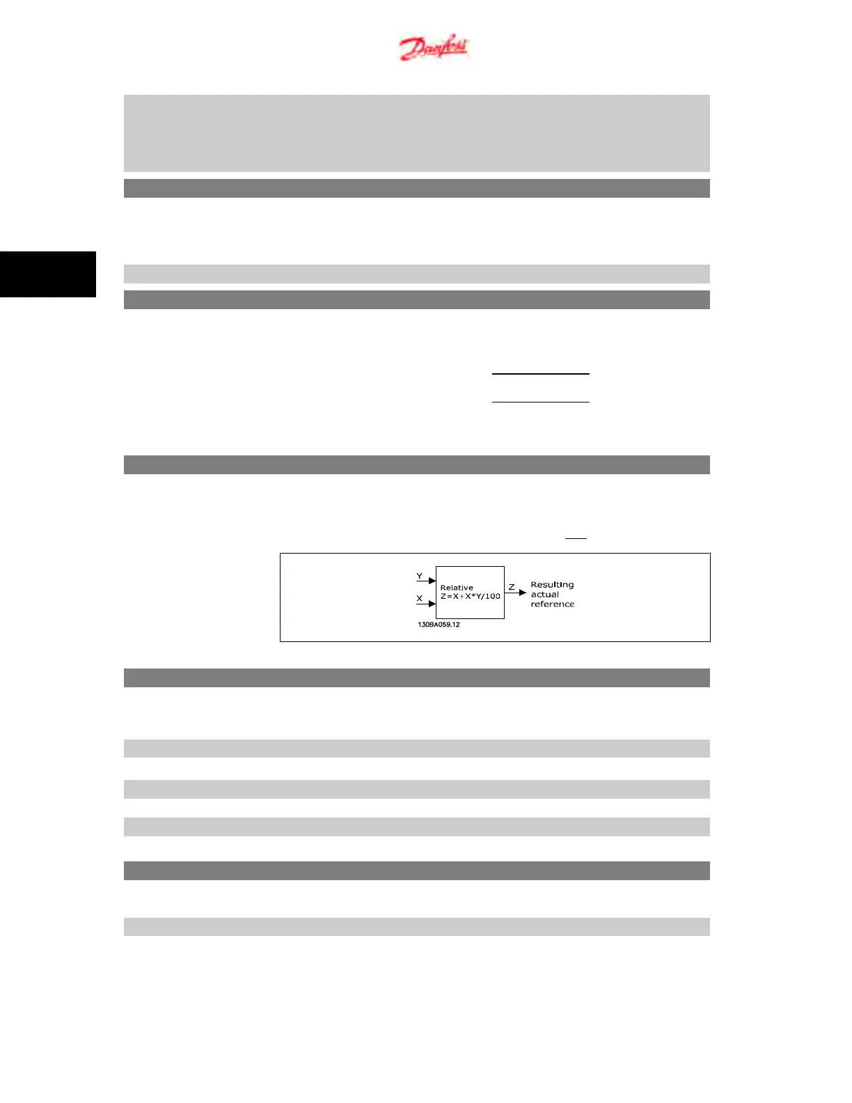
3-14 Preset Relative Reference
Range: Function:
0.00% [-100.00 - 100.00%] Define fixed value in % to be added to variable value defined in par. 3-18,
Relative Scaling Reference Source
.
The sum of fixed and variable values (labelled Y in illustration below) is multiplied with actual reference (labelled
X in illustation). This product is added to actual reference
X
+
X
×
Y
100
3-15 Reference 1 Source
Option: Function:
Par. 3-15, 3-16 and 3-17 define up to three different reference signals. The sum of these reference signals
defines the actual reference.
[0] No Function No reference signal is defined.
[1]
*
Analog Input 53 Use signals from analog input 53 as reference, see par. 6-1*.
[2] Analog Input 60 Use signals from analog input 60 as reference, see par. 6-2*.
[8] Pulse input 33 Use signals from pulse input as reference, see par. 5-5*.
[11] Local Bus Reference Use signals from local bus as reference, see par. 8-9*.
[21] LCP Potentiometer Use signals from LCP potentiometer as reference, see par. 6-8*.
3-16 Reference 2 Source
Option: Function:
See Par. 3-15 for description.
[0] No Function No reference signal is defined.
[1] Analog Input 53 Use signals from analog input 53 as reference.
4. Parameter Descriptions VLT
p
Micro Drive FC 51
26
MG.02.C4.02 - VLT
p
is a registered Danfoss trademark
4
 Loading...


