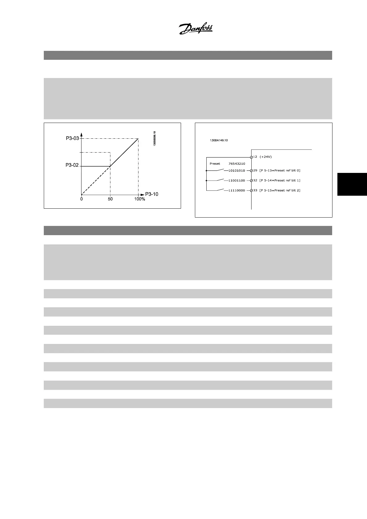
3-10 Preset Reference
Array [8]
Range: Function:
0.00 %* [-100.00 - 100.00 %] Enter up to eight different preset references (0–7) in this parameter, using array programming. The
preset reference is stated as a percentage of the value Ref
MAX
(par.3-03
Maximum Reference
, for
closed-loop see par. 20-14
Maximum Reference/Feedb.
). When using preset references, select Pre-
set ref. bit 0 / 1 / 2 [16], [17] or [18] for the corresponding digital inputs in parameter group 5-1*
Digital Inputs.
3-15 Reference 1 Source
Option: Function:
Select the reference input to be used for the first reference signal. par.3-15
Reference 1 Source
,
par.3-16
Reference 2 Source
and par. 3-17
Reference 3 Source
define up to three different reference
signals. The sum of these reference signals defines the actual reference.
This parameter cannot be adjusted while the motor is running.
[0] No function
[1] * Analog input 53
[2] Analog input 54
[7] Pulse input 29
[8] Pulse input 33
[20] Digital pot.meter
[21] Analog input X30/11
[22] Analog input X30/12
[23] Analog Input X42/1
[24] Analog Input X42/3
[25] Analog Input X42/5
[30] Ext. Closed-loop 1
[31] Ext. Closed-loop 2
[32] Ext. Closed-loop 3
VLT
®
HVAC Drive Instruction Manual
6 How to program the adjustable frequency
drive
MG.11.A9.22 - VLT
®
is a registered Danfoss trademark
6-27
6