149
MG.10.J8.02 – VLT is a registered Danfoss trade mark
Programmable SyncPos motion controller
Syntax Example
SETCURVE curve
SYNCCMM 1 // Synchronize 1 x in CAM mode
// with marker correction
Sample
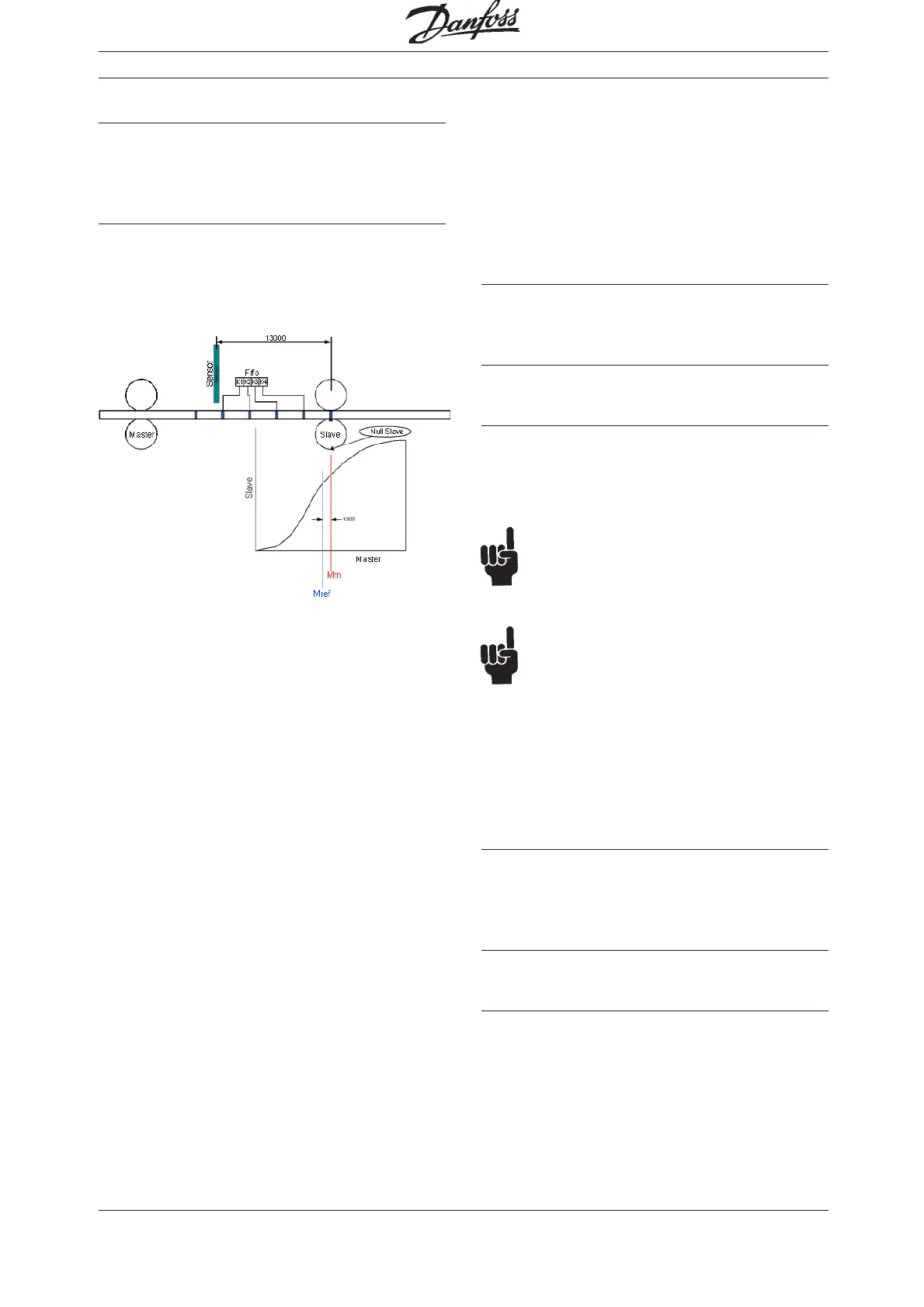
If for example curve length is 3000 and distance of
sensor to working point is 13000, we will have a
FIFO with 4 register and an offset of 1000 which
has to be concerned.
See the following diagram:
■■
■■
■ SYNCCMS
Like SYNCC, the command SYNCCMS brings
about a synchronization in CAM-Mode, but beyond
that it also performs a marker correction of the
slave. Here, the slave position is corrected, not the
curve position.
In contrast to SYNCCMM, no FIFO is created.
Summary
Synchronization in CAM-Mode with slave marker
correction
Syntax
SYNCCMS num
Parameter
num = number of curves to be processed;
0 = the drive remains in CAM-Mode until
another mode is started with commands
such as MOTOR STOP, CSTART, POSA etc.
NB!
SYNCCMS does not start the slave drive nor
does it interrupt on-going motions (e.g. CVEL),
only SYNCCSTART does.
NB!
The drive remains in CAM-Mode until num
curves have been processed successfully.
If the synchronization (after num curves) is being
closed normally, the start stop point pair 2 will be
used – if no SYNCCSTOP with a corresponding
point pair is defined – in order to stop the drive. It
will then come to a stop at the position slavepos
(see parameters).
Marker signal
The marker can be the zero pulse from the enco-
der or an external 24 volt signal:
I5 =master; I6 = slave
Command Group
CAM
Syntax Example
SETCURVE curve
SYNCCMS 0 // Synchronization in CAM-Mode
// with slave marker correction
Software Reference