Programmable SyncPos motion controller
MG.10.J8.02 – VLT is a registered Danfoss trade mark
46
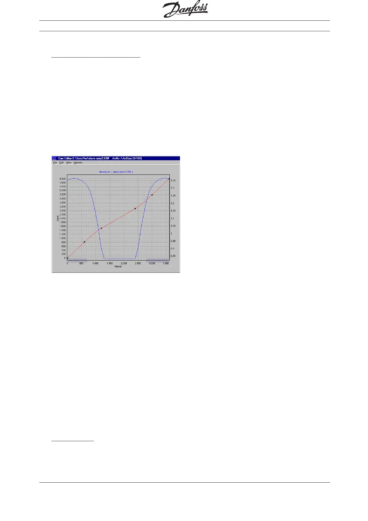
Points Master Slave Type
10 01
2 600 813 1
3 1200 1500 2
4 2400 2500 2
5 3000 3186 1
6 3600 4000 1
Activate the diagram of the → "VELOCITY"
and move the two newly inserted fixpoints with
the help of the mouse until you get a uniform
velocity progression:
8. Enter the → "CYCLES/MIN MASTER" = 20 in
the index card → "CURVE INFO". This is the
(maximum) number of cardboard boxes that
can be processed per minute.
9. Verify whether the acceleration of the slave is
within the limit. For this purpose, you must
activate the illustration of the
→ "ACCELERATION" and of the
→ "ACC. LIMIT".
10. Define in the index card → "START STOP
POINTS" with some safe distance in order to
start the synchronization at the beginning.
Engaging should take place between 20 and
100 degrees because it must be completed at
120 degrees.
Points Master
1a 200
1b 1000
11. In the index card → "CURVE DATA", define the
position where the conveyor belt should stop if
no other Slave Stop Position is being defined in
the program:
The conveyor belt should always stop in
position 0:
→ "SLAVE STOP POSITION" = 0
12. The photoelectric beam (external marker) has a
distance of 390 mm from the processing point
(= stamp touches the box) and detects the
beginning of the box (corresponds to slave
position 1000). Thus, the marker distance is
3900. Enter this value in the index card →
"SYNCHRONIZATION" and define the permit-
ted tolerance for the appearance of the mar-
kers and the external marker type = 2 for the
slave:
Slave Marker
Distance SYNCMPULSM (59) = 3900
Tolerance SYNCMWINM (69) = 200
Type SYNCTYPM (61) = 2
Enter the values in the index card → "CURVE
DATA":
Slave-Marker-Position = 1000
13. Take a look at the curve profile in order to
determine when the correction of the synchro-
nization may begin at the earliest and when it
must be finished. The green horizontal line
indicates the master position where the mar-
ker is recognized, the light green area shows
the tolerance window for the appearance of
the master marker.
(See PC-Software for colour.)
At the earliest, the correction may begin when
the printing of a cardboard box has been
completed, since any change of velocity
during the printing process would damage the
printing stamp and/or the box. Also, the cor-
rection must have been completed in its
entirety when the next box arrives at the pro-
cessing point. In this example, the slave posi-
tions at the end and beginning of a box are
quite suitable.
Enter the values in the index card → "CURVE
DATA":
Correction Start = 2800
Correction End = 750
CAM Control