DM4270 – Installation Guide
204.4331.03 - October/2019
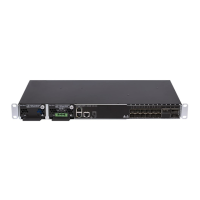
PSU 400 AC insertion and removal latch
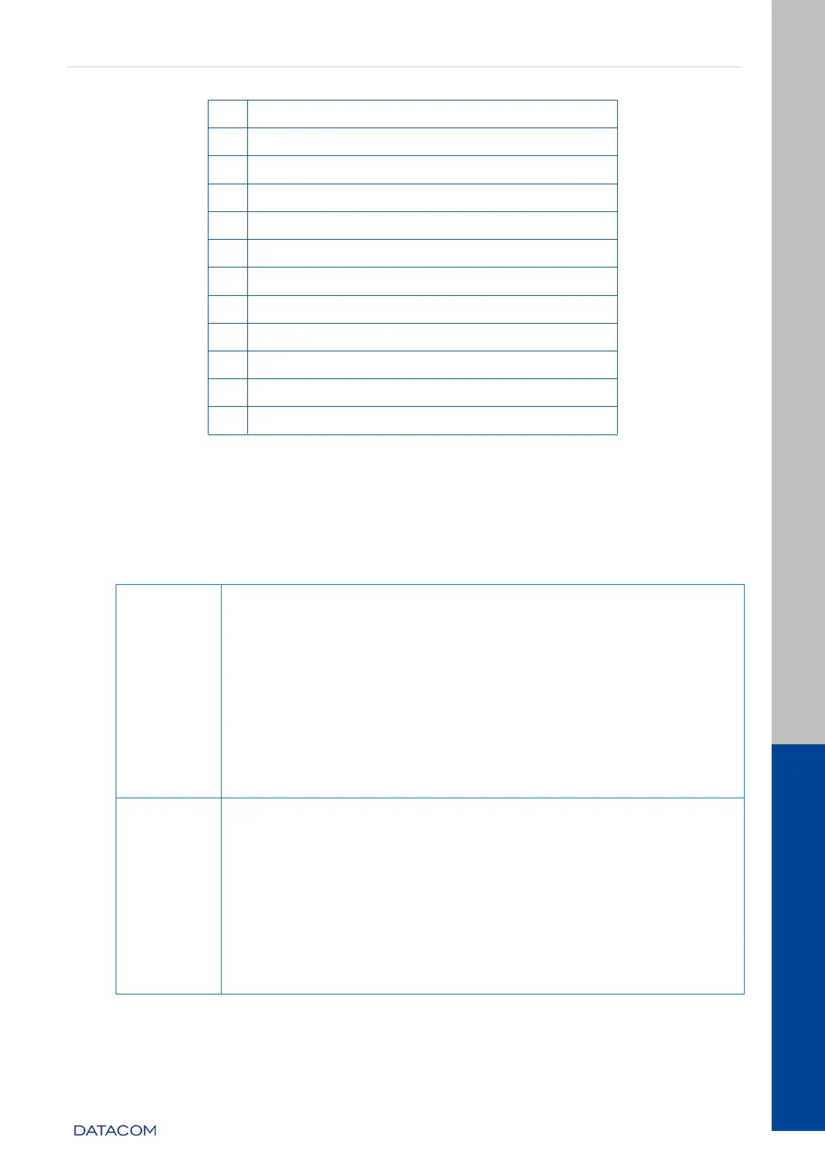
Table 2 –DM4270 48XS+6CX Interface Description
3.4 EQUIPMENT STATUS LEDS
The DM4270 Switch has two statuses indicating LEDs in the front panel, the LED
ALARM/FAIL located in the Mainboard and the LED PWR located in each PSU. The table
below describes the behavior of the status LEDs of the equipment.
PSU 400 DC
ON GREEN: Indicates that the power supply is running and that
the equipment is powered or on standby ready to take over the
load.
OFF: Power supply with problems or not powered.
PSU 400 AC
ON GREEN: Indicates that the power supply is running and the
equipment is powered or on standby ready to take over the
load.
ON AMBER: Indicates that the power supply is powered, but is
disconnected from the HW or on standby.
OFF: Power supply with problems or not powered.
OFF: Equipment operating normally, without detected failures
or alarms.
ON RED: Indicates that the equipment is in a state of internal
failure.
ON BLINKING RED (slow): Indicates that the equipment is in a
lower gravity alarm state.
ON BLINKING RED (fast): Indicates that the equipment is in a
lower gravity alarm state.
When the power is connected to the equipment, this LED will turn
red for a short time, and then will turn off.
Table 3 - Status LED behavior