DM4270 – Installation Guide
204.4331.03 - October/2019
voltage difference between IN+ and IN- reaches 12V. The Table 10 presents the
voltages and status for alarm 1 and 2 inputs.
Table 10 – Conditions for alarm detection
For alarm output, the equipment uses a relay. In an alarm situation
or when the switch
is off, pin 7 (common) is short circuited with pin 8 (NF). When operating without alarms,
pin 7 (common) will be short circuited with pin 6 (NA), while pin 8 (NF) will be isolated.
The table below describes the pin settings used in connector RJ45 of the alarm
interface.
Table 11 - Alarm pin connector
The DM4270 48XS+6CX does not have alarm ports.
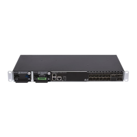
3.11 PSUS AND POWER INPUTS
The equipment of the DM4270 line has two slots for the PSU 400 power supply
(supplied separately).
The DM4270 family has four PSU models as shown in the table below:
Table 12 – Description of PSU 400 power supplies
The DM4270 24XS+2CX only supports PSU 400 AC-B and PSU 400 DC-B power supply
versions, because it only has one cooling direction.
The PSU 400 DC has TERMINAL BLOCK power terminals.
Roadmap feature, contact Technical Support if you have any questions.