DM4270 – Installation Guide
204.4331.03 - October/2019
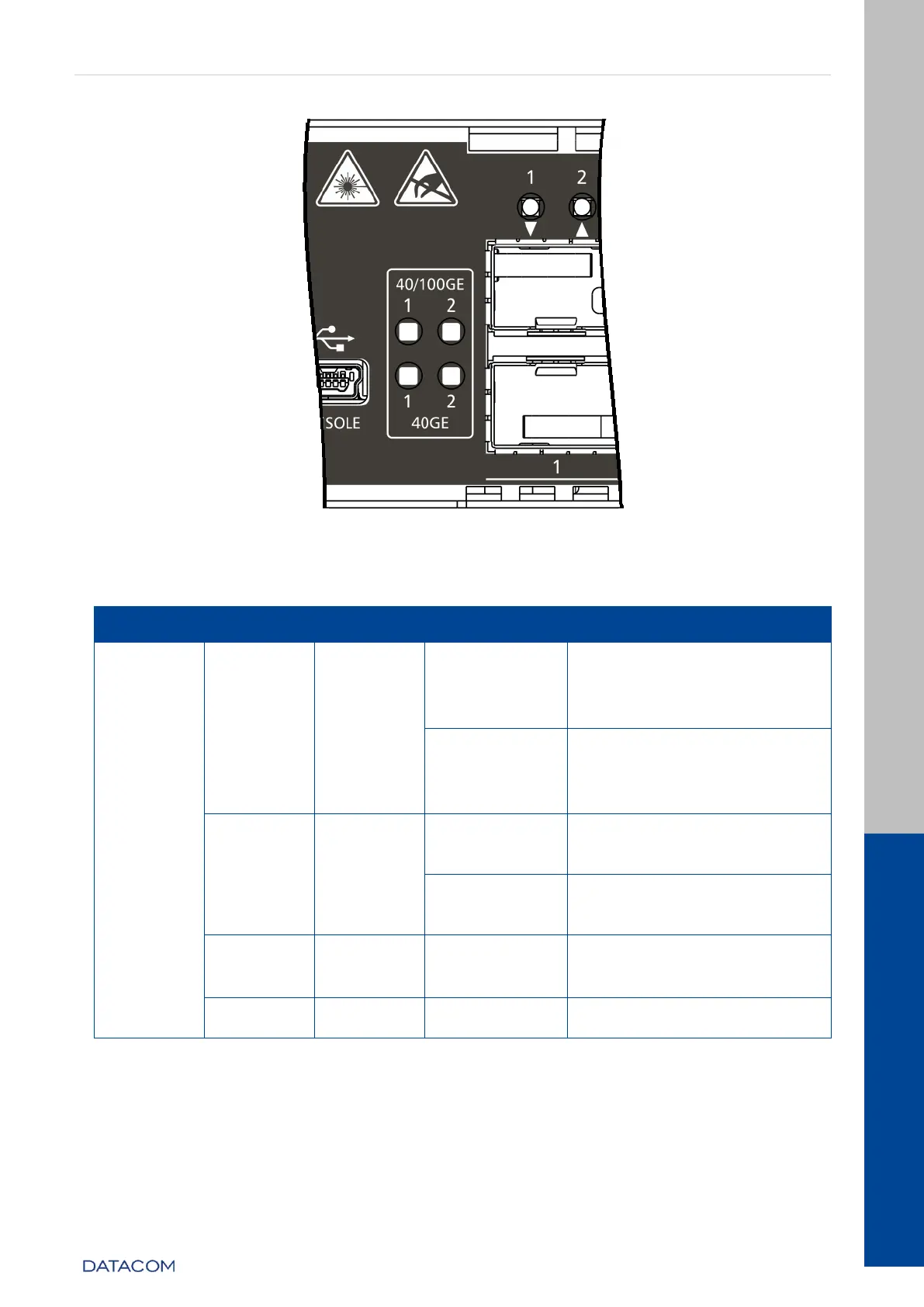
Figure 13 – 40GE and 100GE port LEDs
Link Up (active port)
operating in 100GBase-X
mode.
Link Up (active port)
operating in 40GBase-X
mode.
Link Up (active port)
operating at a rate lower
than 100GE.
Link Up (active port)
operating at a rate lower
than 40GE.
Data sending and/or
receiving activity
Link Down (inactive port)
Table 9 - 40GE and 100GE Interface LED indicators
3.10 ALARM INPUT AND OUTPUT
The DM4270 has two alarm inputs and one alarm output in an RJ45 connector. Alarm 1
and 2 inputs are isolated via optocoupler. External alarm detection occurs when the