DM4270 – Installation Guide
204.4331.03 - October/2019
3.9.2 DM4270 24XS+2CX
3.9.2.1 10 Gigabit SFP+ Optical Ethernet Interfaces (10GBase-X)
The DM4270 24XS+2CX has 24 10 Gigabit Optical Ethernet interfaces using SFP+
connectors. The status indicating LED contains the LINK/ACT/SPEED information on the
same bicolor LED.
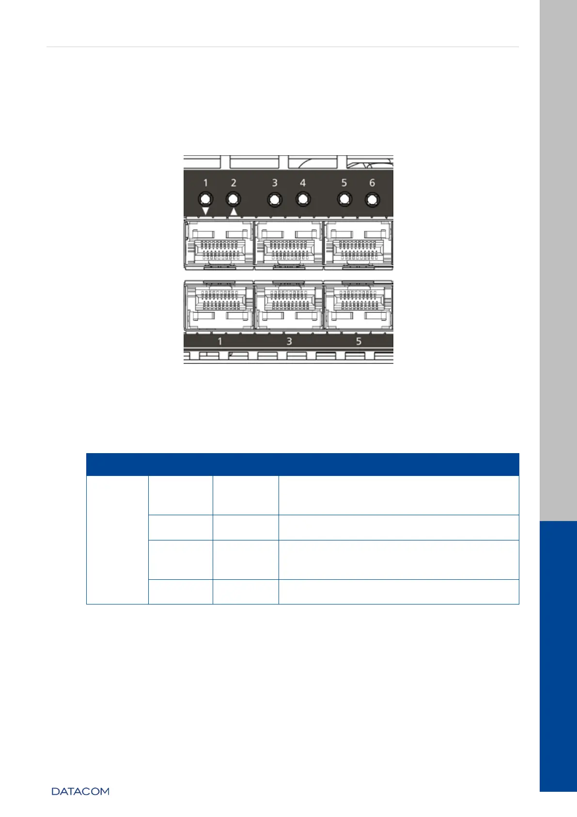
Figure 11 - 10GE SFP+ Port LEDs
3.9.2.2 10 Gigabit Optical Ethernet Interface LED indicators
The convention to indicate the operation and mode of operation of the 10GE SFP+
interfaces is described in the table below:
Link Up (active port) operating in
10GBase-X mode.
Link Up (active port) operating at a rate
lower than 10GE.
Data sending and/or receiving activity
Table 8 - 10GE SFP+ Interface LED indicators
3.9.2.3 40 and 100 Gigabit Optical Ethernet Interfaces
The DM4270 24XS+2CX has 4 high-speed interfaces using QSFP+ e QSFP28
connectors.
Due to the equipment’s architecture, there are 3 valid configurations for the uplink
ports:
2 x 40/100 optical Gigabit Ethernet ports (QSFP28)