DM4270 – Installation Guide
204.4331.03 - October/2019
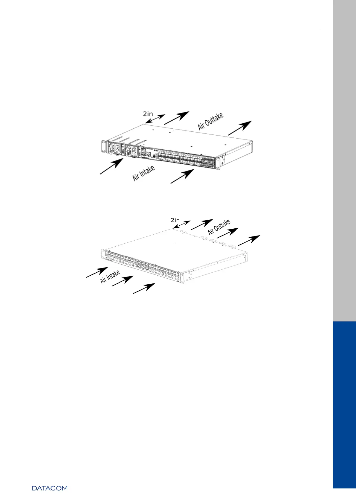
operation of the cooling system it is important that the air inlets and outlets are
unobstructed and that the free areas of 5cm are respected on the rear panel and on the
left side of the switch. These areas must have free air circulation so that the
temperature of the equipment remains within the assured levels of operation, also
observing the cooling of the environment.
Figure 27 – Air flow in the DM4270 24XS+2CX
Figure 28 – Air flow in the DM4270 48XS+6CX
4.6.1 Installing the removable cooling modules in the
DM4270 48XS+6CX
Unlike the DM4270 24XS+2CX, the DM4270 48XS+6CX has independent hot-swappable cooling modules.
For the correct operation of the system, all 4 modules must be connected to the equipment, therefore blank
panels are not available as accessories.
Each cooling module has two knurled screws to secure the equipment, if necessary, use a screwdriver to
insert and remove the modules.