ALTERNATIVE CONNECTIONS FOR SERIAL MODELS
USER INTERFACE - SERIAL HOST
RS232 PC-side connections
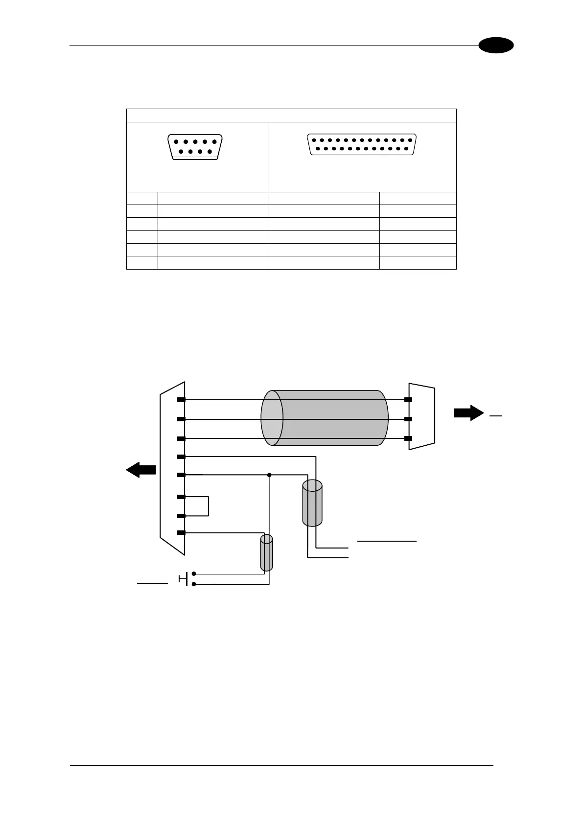
How To Build A Simple Interface Test Cable:
The following wiring diagram shows a simple test cable including power, external (push-
button) trigger and PC RS232 COM port connections.
Power Supply
Vdc (10 – 30 Vdc)
Power GND
Figure 80- Test Cable for Serial Model Scanners