DX8200A QUICK GUIDE
12
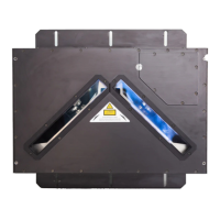
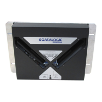
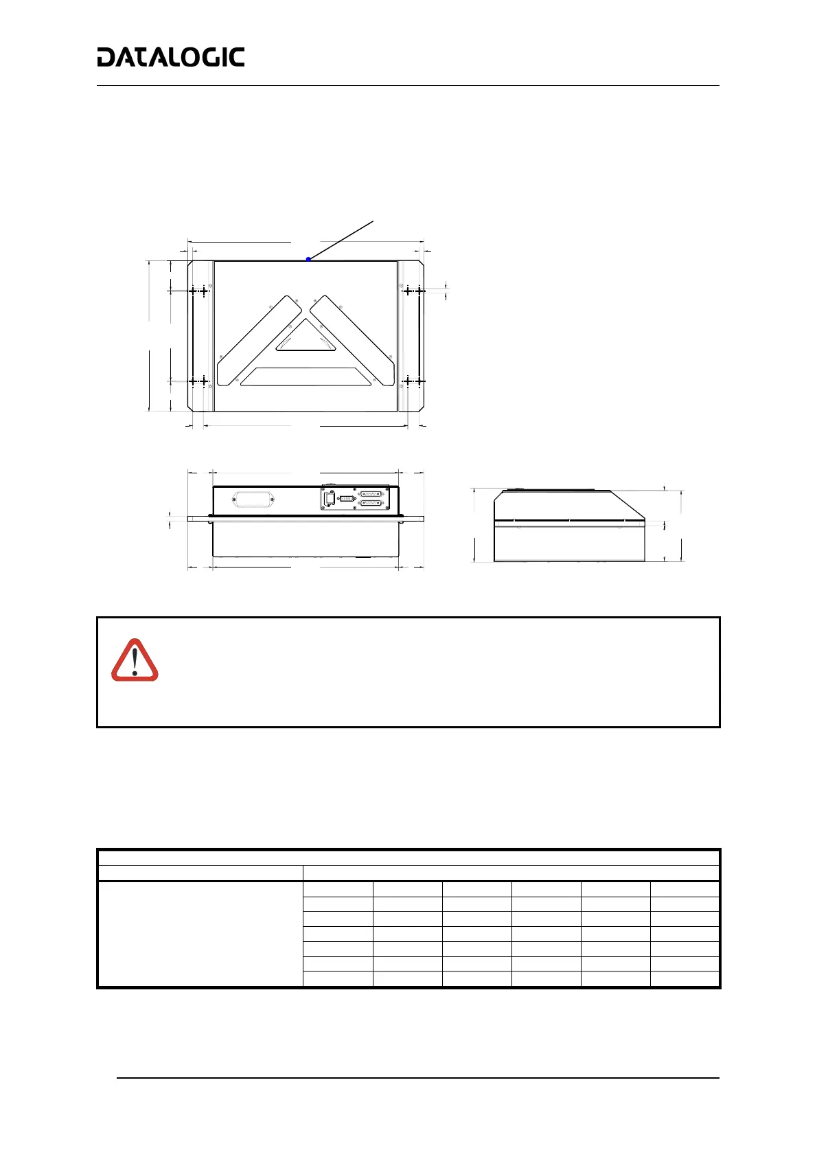
Mechanical Installation:
DX8200A can be installed to operate in any position. There are 4 slots (dia. 8.5 mm) on the sides of the scanner
for mounting. The diagram below can be used for installation; refer to the Reading Diagrams for correct positioning of
the scanner with respect to the reading zone and scanner orientation.
470
[18.50]
300
[11.81]
==
180
[7.09]
22
[0.87]
406
[15.98]
22
[0.87]
8.5
[0.33]
141
[5.55]
147
[5.79]
10
[0.39]
370
[14.57]
==
370
[14.57]
= =
==
60.5
[2.38]
70.5
[2.78]
N° 4
DX8200A Overall Dimensions
WARNING
When installing several scanners, take care to position them correctly so that no laser beam
enters the reading window perpendicularly and at the same level of the output beam of the
other scanners. This condition could occur more frequently for side mounted applications. If
these precautions are not followed, it may occur that the laser of the blinded scanner starts
blinking due to an internal circuit which temporarily turns the laser off when detecting a power
anomaly. To resolve this problem, it is sufficient to slightly change the inclination and position
of one of the two scanners involved.
Reading Conditions:
• ANSI Grade B minimum
• 500 scans/sec per leg
The following tables describe the requirements for standard applications.
Minimum Code Height for Omnidirectional Reading (mm)
Conveyor Speed (m/s) 0.5 1 1.5 2 2.5 3
0.25
11 13 15 17 19 21
0.30
12 14 16 18 20 23
0.33
13 15 17 19 21 23
0.38
14 16 18 20 23 25
0.50
18 19 22 24 26 28
0.72
24 26 27 29 32 34
2/5 Interleaved
Code Resolution (mm)
1.00
33 34 35 37 39 41
Ratio 3:1
Table 1
PackTrack™ Coordinate Reference Point
where x, y, z = 0
 Loading...