DX8200A QUICK GUIDE
5
Electrical Connections:
The details of the connector pins are indicated in the following tables:
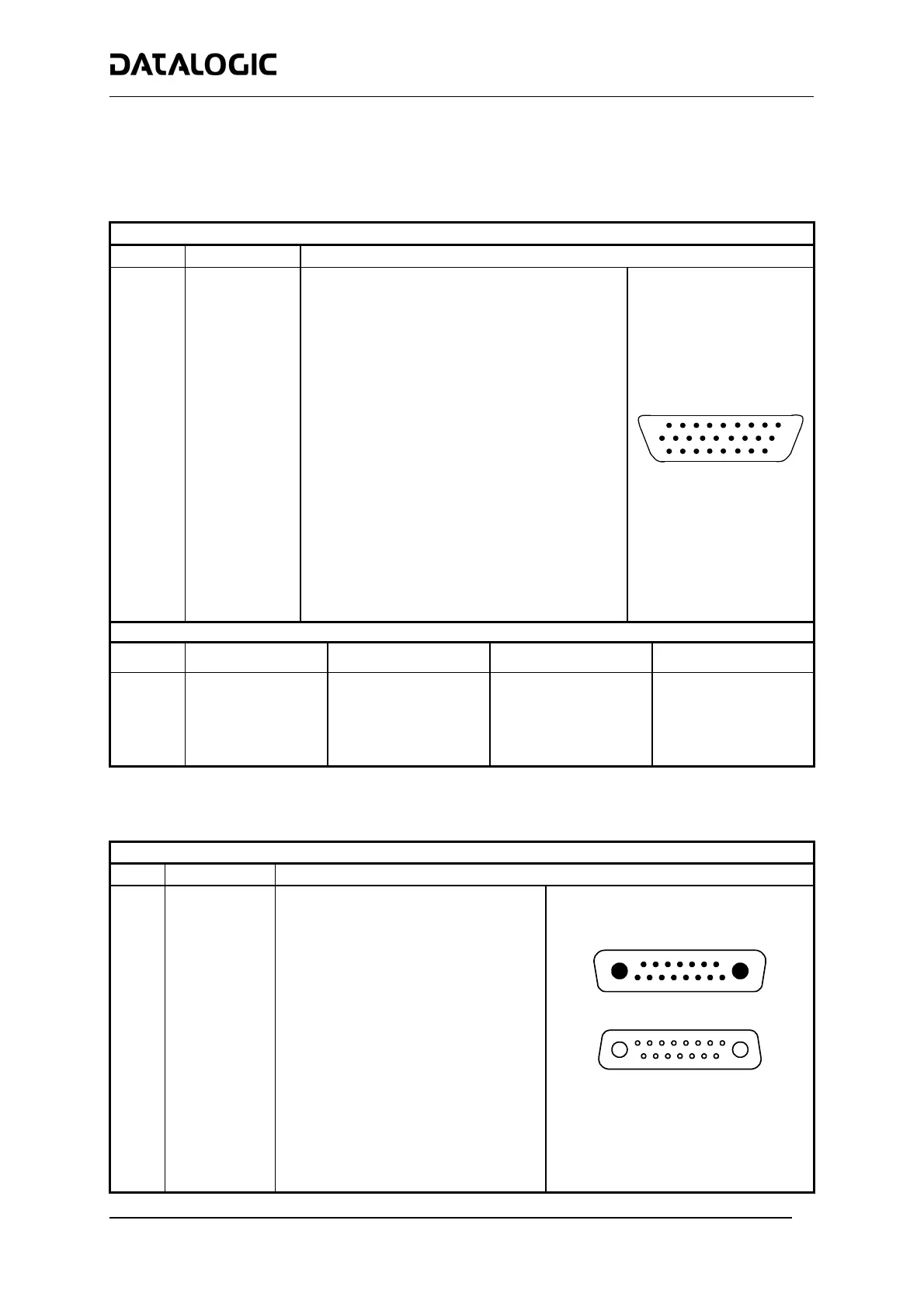
The DX8200A scanner provides a 26-pin male D-sub connector for connection to power supply, Host interface
(Main and Aux), and input/output signals.
26-pin D-Sub Connector Pinout
Pin Name Function
Chassis - internally connected to GND
1 CHASSIS
Cable shield connected to chassis
20 RXAUX Receive data of auxiliary RS232 (referred to GND)
21 TXAUX Transmit data of auxiliary RS232 (referred to GND)
8 OUT 1+ Configurable digital output 1 – positive pin
22 OUT 1- Configurable digital output 1 – negative pin
11 OUT 2+ Configurable digital output 2 – positive pin
12 OUT 2- Configurable digital output 2 – negative pin
16 OUT 3A Configurable digital output 3 – polarity insensitive
17 OUT 3B Configurable digital output 3 – polarity insensitive
18 EXT_TRIG/PS A External trigger (polarity insensitive) for PS
19 EXT_TRIG/PS B External trigger (polarity insensitive) for PS
6 IN2/ENC A Input signal 2 (polarity insensitive) for Encoder
10 IN2/ENC B Input signal 2 (polarity insensitive) for Encoder
14 IN3A Input signal 3 (polarity insensitive)
15 IN4A Input signal 4 (polarity insensitive)
24 IN_REF Common reference of IN3 and IN4 (polarity insensitive)
9, 13 VS Supply voltage – positive pin
23, 25, 26 GND Supply voltage – negative pin
10
19
1
18
9
26
26-pin male D-sub Connector
Main Interface Connector Pinout
Pin RS232 RS485 Full-Duplex RS485 Half-Duplex
20 mA C.L.
(INT-30 with C-BOX 100 only)
2 TX TX485+ RTX485+
3 RX RX485+
4 RTS TX485- RTX485-
5 CTS RX485-
7 GND_ISO GND_ISO GND_ISO
see INT-30 instructions
Two 17-pin connectors provide access to the scanner’s local Lonworks network used for both input and output
connections to build a multi-sided or omni-station system.
17-pin Lonworks Connector Pinout
Pin Name
Function
A1 GND Supply voltage (negative pin)
A2 VS Supply voltage 20 to 30 Vdc (positive pin)
Cable shield A - internally connected by
1 CHASSIS
capacitor to chassis
2 n.c. Not connected
Cable shield B - internally connected by
3 CHASSIS
capacitor to chassis
4 n.c. Not connected
5 n.c. Not connected
6 n.c. Not connected
7 VS_I/O Supply voltage of I/O circuit
8 Lon A+ Lonworks a line (positive pin)
9 Lon A- Lonworks a line (negative pin)
10 Lon B+ Lonworks b line (positive pin)
11 Lon B- Lonworks b line (negative pin)
12 SYS_I/O System signal
13 SYS_ENC_I/O System signal
14 Reserved Internally connected
15 Ref_I/O Reference voltage of I/O circuit
A1
A2
1
15
Female - Output
A1
A2
1
15
Male - Input
17-pin Local Lonworks Connectors