SETUP
18
QUICKSCAN™ 2500
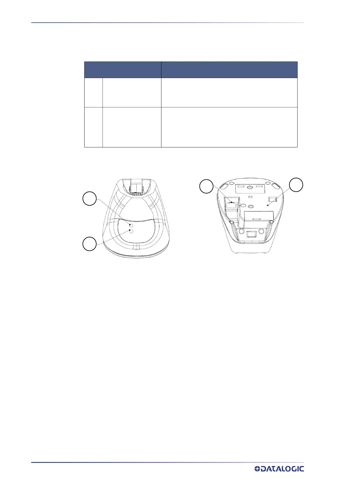
Two LEDs on the BC2090 Radio Base provide information about the Base as well as bat-
tery charging status, as illustrated in the following table:
Table 2 - Radio Base LEDs
Figure 9 -
QuickScan Cradle LEDs, Communication Port and Service Button Description
LED STATUS
1 Power ON / Data
Green On = Base is powered
Green Blinking = Base receives data and commands
from the Host or the Reader.
2 Charging
Green On = the battery is completely charged
Green blinking = battery level 51 to 99%
Amber blinking = battery level 1 to 50%
Red blinking = pre-charge
1. Power LED 3. Communication Port
2. Battery Charging Status 4. Service Button
2
1
3
4
 Loading...