RSS_v180808n RSS Series Page 11
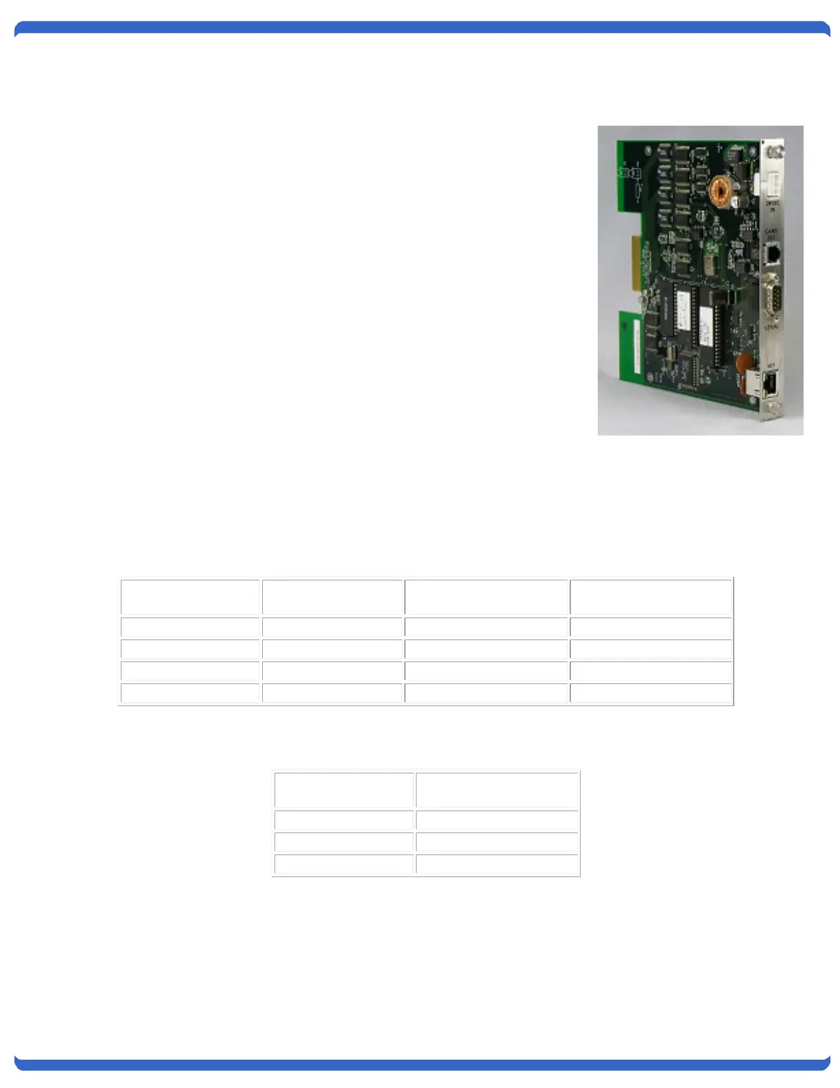
4.2. IPC-16-R Installation
The IPC-16-R Control Card installs from the rear of the chassis in one of the
two control card slots only. The slot are on the left (facing the rear), next to the
power supply. Two IPC-16-R cards can be installed for redundant remote
access. Note: It is recommended that any removal or insertion of a control card
be performed with power off to prevent possible unintentional switching of the
switch cards.
The card provides the following connections:
External Power Input. Connection for external power supply, singularly, or as
a supplement to an internal supply for dual redundant power. Mating
Connector kit # 1940164
Gang Expansion. RJ11 connection for connection to additional chassis for
large gang switching applications.
Serial Port. RS-232 port for out-of-band access to the IPC-16-R card.
Ethernet. Network connection; 10baseT - IPC-16-R,
4.3. Serial Port
The Serial Port on the control card is a 9 pin male connector, configured as a DTE. The following pins are used.
The following chart illustrates the pin out of the D9 connector and the connection required to an external modem
with a D25 pin out.
D9 Pin
Abbreviation Full Name
For connection directly to a terminal, a Null Modem cable is required.