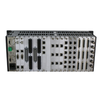
RSS_v180808n RSS Series Page 33
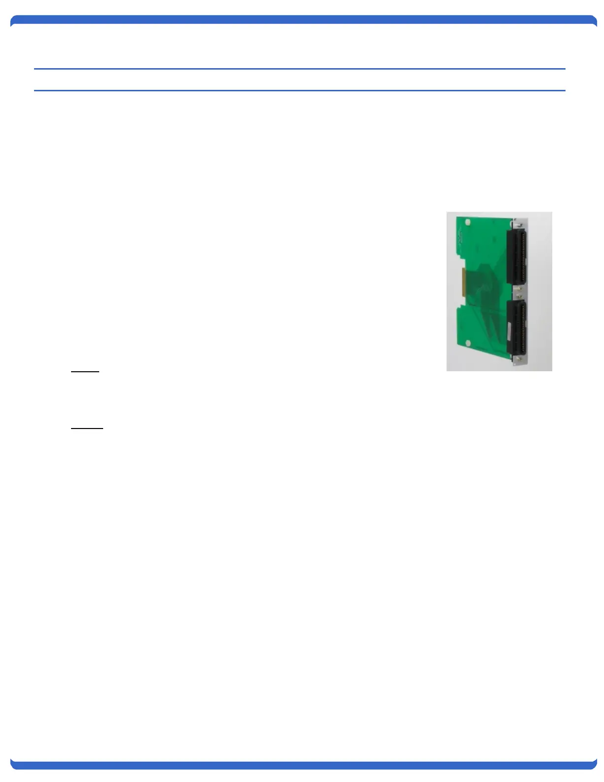
6. IOC-16-R 16 Channel I/O Control Card
Item # 1340067
The IOC-16-R #1340067 provides wiring access for external contact control and switch card status monitoring. It
can be installed along with a IPC-16-R Network Control access card or with a IOC-16-R gang access card.
6.1. Installation
The IOC-16-R installs in from the rear of the chassis in the leftmost control card slot
only, 3
rd
slot from the left in the rear of the chassis. Install the card with the
components facing left. The IOC-16-R may be inserted and removed with the
power on (hot insertion/removal) , but use caution as any contact wiring connected
to the IOC card may cause unintended switch card changes. Make sure to use the
screws provided to secure the card in the chassis before connecting cables.
6.2. Status and Control Connector Pinouts
The following pinouts detail the connections necessary for individual and gang
control of each A/B card, as well as the available status contacts.
Status
Status is dry relay contacts:
Common not connected to Normally Open (NO) = Switch in Position A
Common connected to Normally Open (NO) = Switch in Position B
Control
For control, momentarily connect the appropriate pin to Ground, for example, To switch Card Slot 2:
Connect Pin 2 to Ground to switch to A
Connect Pin 27 to Ground to switch to B
Use Pins 17 and 42 to switch all card slots simultaneously.
The complete pinout of these connectors follows on the next page.