RSS_v180808n RSS Series Page 4
Note for serviceperson/technician: The symbol left
(exclamation point in a triangle) indicates that energy
hazards could be possible on the backplane. The
symbol is located on the inside of the chassis near
every other A/B switch connector.
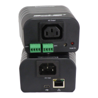
This symbol located by the power inlets indicates
that these devices may have multiple power sources.
It is required that all power sources shall be
disconnected before servicing to avoid shock hazard
Remarque pour préposé à l'entretien / technicien: Le symbole à
gauche (point dans un triangle d'exclamation) indique que les
dangers de l'énergie pourrait être possible sur le fond de panier. Le
symbole est situé à l'intérieur du châssis à proximité de chaque
autre connecteur du commutateur A / B.
Ce symbole situé par les entrées d'alimentation indique que ces
dispositifs peuvent avoir plusieurs sources d'alimentation. Il est
nécessaire que toutes les sources d'alimentation doivent être
déconnectés avant l'entretien pour éviter tout risque de choc.
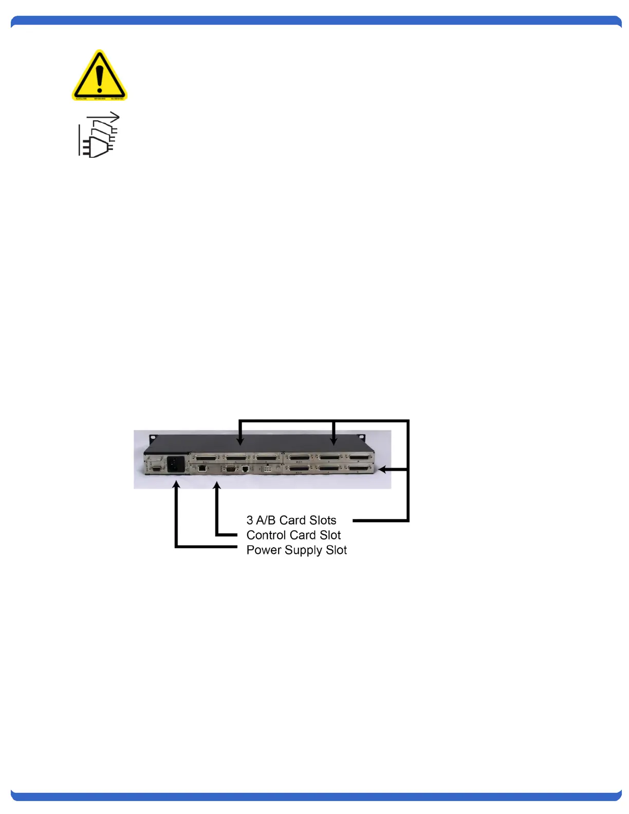
2.3. RSS-3 Chassis
Item # 1150102
The RSS-3 Chassis mounts in standard 19” equipment cabinets. Rack mounting brackets provided, can be
attached to the chassis sides for front or rear rail installations, or removed for non rack applications.
Power supplies, control cards and switch cards install from the rear of the chassis. Install each card into the guide
slots with the components facing upwards. The chassis and cards are keyed to prevent incorrect insertion. Switch
cards may be inserted and removed with the power on (hot insertion/removal). Cards are secured in chassis with
screws at right and left of each panel.
19" W x 1.75" H x 7" D Weigh 3.5 lbs. (w/o cards)
2.4. Power Supply Indicators
The Chassis has two LED indicators that display the current status of two power supply sources. These are
designated PS-1 and PS-2. LED on Indicates the power supply source is connected.
PS-1 Internal Power Supply Module, or External Power Supply #1
PS-2 Internal Power Supply Module, or External Power Supply #2