RSS_v180808n RSS Series Page 39
8.3.2. Frame Ground Switching – Model AB-D25-R
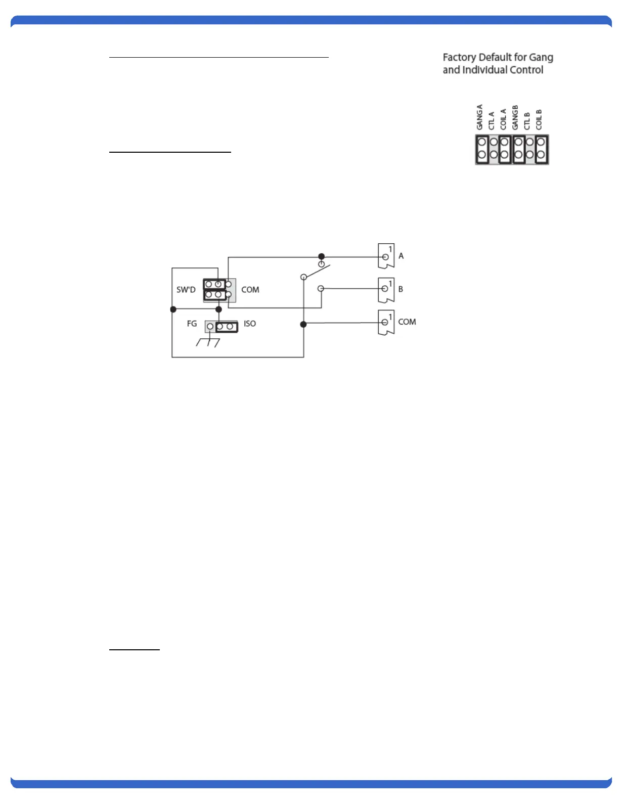
Jumper selection allows Pin 1 Frame Ground to be either switched or tied
together and non-switched. Pin 1 can also be tied to the Frame of the
Chassis, or left isolated from the chassis.
8.3.3. Signal Ground Switching
An additional set of jumpers provides the same switched/common, isolated or
grounded for Signal Ground. These jumpers control Pin 7 in the D25 model and Pin 5 in the D15 and D9
models. The circuit is the same as shown above replacing Pin 1 for the correct pin and SG Signal Ground for
FG, Frame Ground.
8.4. Indicators
Two Red LEDs indicate Switch status A or B. LED's are driven by extra relay contacts.
8.5. Manual Switches
Manual toggle switch on each card. These are momentary switches. Also controlled by RSS-16 front panel
Gang Control pushbuttons when the card’s jumper is configured for Gang control.
8.6. Relays
Sealed Telephone relays. Gold clad contacts. Maximum Contact Current: 2 Amps @ 30 VDC
Special DS-3 and NET models: Hi Freq. Speeds up to 1 Gig Hz.
8.7. Interface Wiring
8.7.1. AB-D25-R
Conectors: 25 Pin D’Subminiature, Female
Leads Supported: All 25 Pins Switched
Additional Information: Optional Jumper Configuration for
Unswitched Frame Ground Pin 1 (See Section 8.4.2) J10
and Signal Ground Pin 7 (See Section 8.4.3) J11