DI-2008 Hardware Manual
Controls, Indicators, and Connections
10
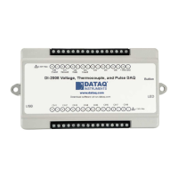
DI-2008 Signal Connections
Refer to the following for screw terminal port identification.
CH#:
Analog channels 1-8 (Programmable ±10, ±25, ±50, ±100, ±250, ±500mV; ±1, ±2.5, ±5, ±10, ±25, ±50
Volts or Thermocouple type J, K, T, B, R, S, E, N; 120V rms max.)
D#: D
igital port (0-6). Can also be used for specific WINDAQ functions (30 Vmax).
D0 Event —
WINDAQ Remote Event Marker (or general-purpose)
D1 Record — W
INDAQ Remote Start/Stop (or general-purpose)
D2 Rate — Rate In
put (or general-purpose)
D3 Count —
Counter Input (or general-purpose)
D4 - D6 — Genera
l-purpose digital ports
+15V: +1
5V out. Max current = 67mA.
GnD: G
round.
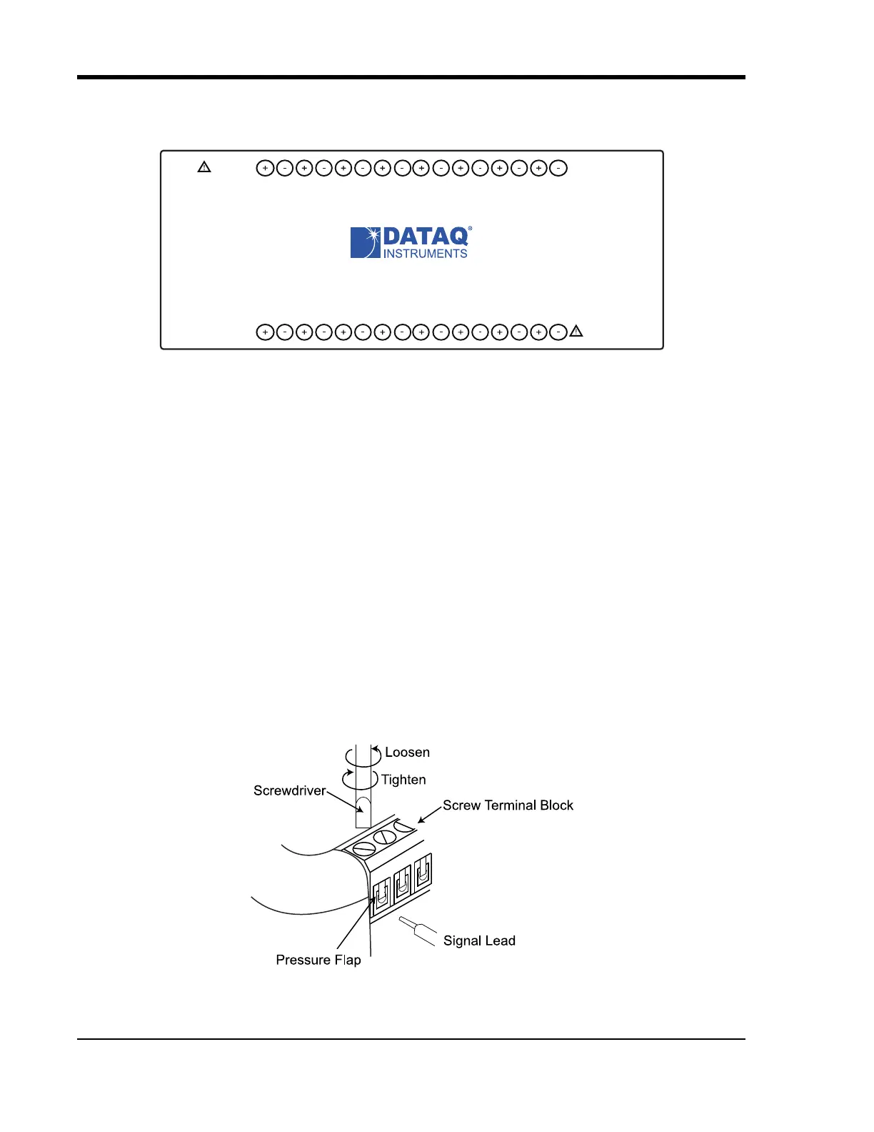
Connecting Signal Leads
Connect signal leads to the DI-2008:
1. Insert the stripped end of a si
gnal lead into the desired terminal directly under the screw.
2. Tighten the pressure flap by rot
ating the screw clockwise with a small screwdriver. Make sure that the pressure
flap tightens only against the signal wire and not the wire insulation. Do not over-tighten.
3. Tug gently on the signal lead to ensure that it is firmly secur
ed.
www.dataq.com
USB
CH8
CH7CH6
CH5CH4CH3CH2CH1
Download software at run.dataq.com
+15V GnD
60mA max
D0 D1 D2 D3 D4 D5 D6
DI-2008 Voltage, Thermocouple, and Pulse DAQ
Button
LED
0-30V Max
CountRateRecordEvent
120V rms max