DI-2008 Hardware Manual
Controls, Indicators, and Connections
11
When an input signal is connected and WINDAQ Acquisition software is run, WINDAQ’s real time display immedi-
ately reveals the input waveform on your computer’s monitor.
Analog Inputs
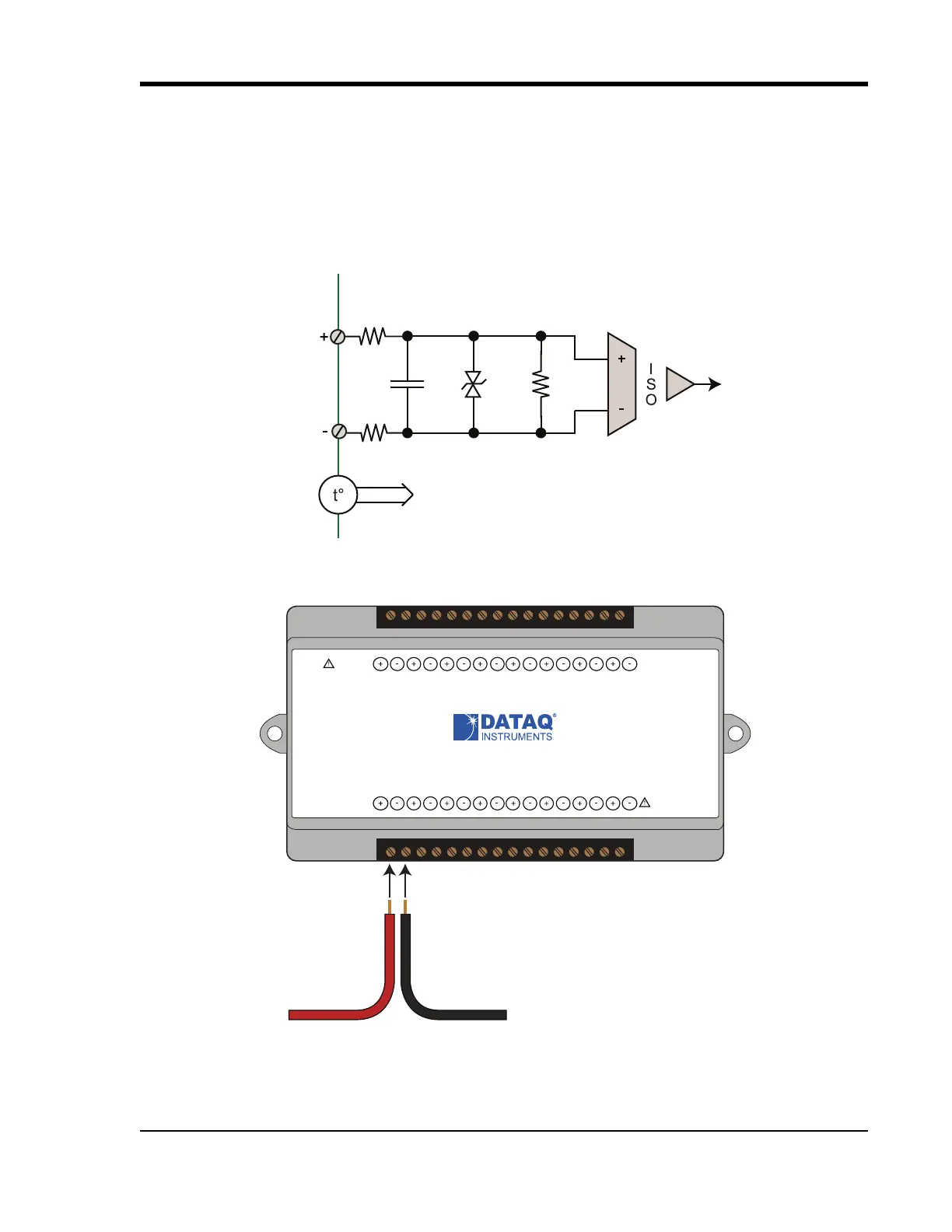
Eight differential analog inputs measure ±10, ±25, ±50, ±100, ±200, ±500mV; ±1, ±2.5, ±5, ±10, ±25, ±50 Volts or
Thermocouple temperatures types J, K, T, B, R, S, E, and N (CH1 to CH8, programmable per channel). Designed to
withstand 120 V rms.
Use the following diagram to connect Analog Input Channel 1.
AIN
49.9
:
AIN
49.9
:
0.047
P
f
150V
1M
:
To CJC Circuitry
www.dataq.com
USB
CH8
CH7CH6
CH5CH4CH3CH2CH1
Download software at run.dataq.com
+15V GnD
60mA max
D0 D1 D2 D3 D4 D5 D6
DI-2008 Voltage, Thermocouple, and Pulse DAQ
Button
LED
0-30V Max
CountRateRecordEvent
120V rms max
Signal +
Signal -