12: Front Panel Assembly
PRC1099A-MS 12-9
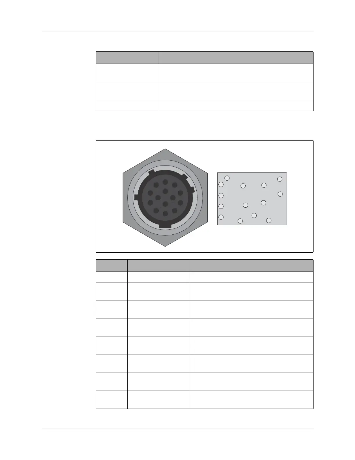
This section provides the Accessory connector pin assignments with a
description of each pin assignment
RA100-12 100W 1.6–30 MHz Linear HF amplifier for 12V system
with MT-1099A-12 vehicle adapter and RAT7000B tuner.
RA100-24 100W 1.6–30 MHz Linear HF amplifier for 24V system
with MT-1099A-12 vehicle adapter and RAT7000B tuner.
RAT7000B 150W automatic antenna tuner.
Pin Name Description
A GND Ground.
B AMP PTT PTT to external 100W RF amplifier RA100-12
or RA100-24 from the Processor board.
C PTT PTT from a handset or headset connected to
either of the front panel Audio connectors.
D TUNE INIT Tune cycle initialization to external antenna
tuner RAT7000B from the Processor board.
E +12V JUMPERED +12 VDC supply voltage jumpered from pin F
using the jumper cap.
F +12V SW +12 VDC supply voltage from the battery
through the Junction board.
H RS232 TXD RS-232 transmit data output signal from the
Processor board.
J TUNER KEYLINE Keyline from the Processor board to an
RAT7000B antenna tuner.
Table 12-3 Supported Accessory Devices
Device Description
B
A
C
D
E
F
H
J
K
L
M
N
P
R