12: Front Panel Assembly
12-8 PRC1099A-MS
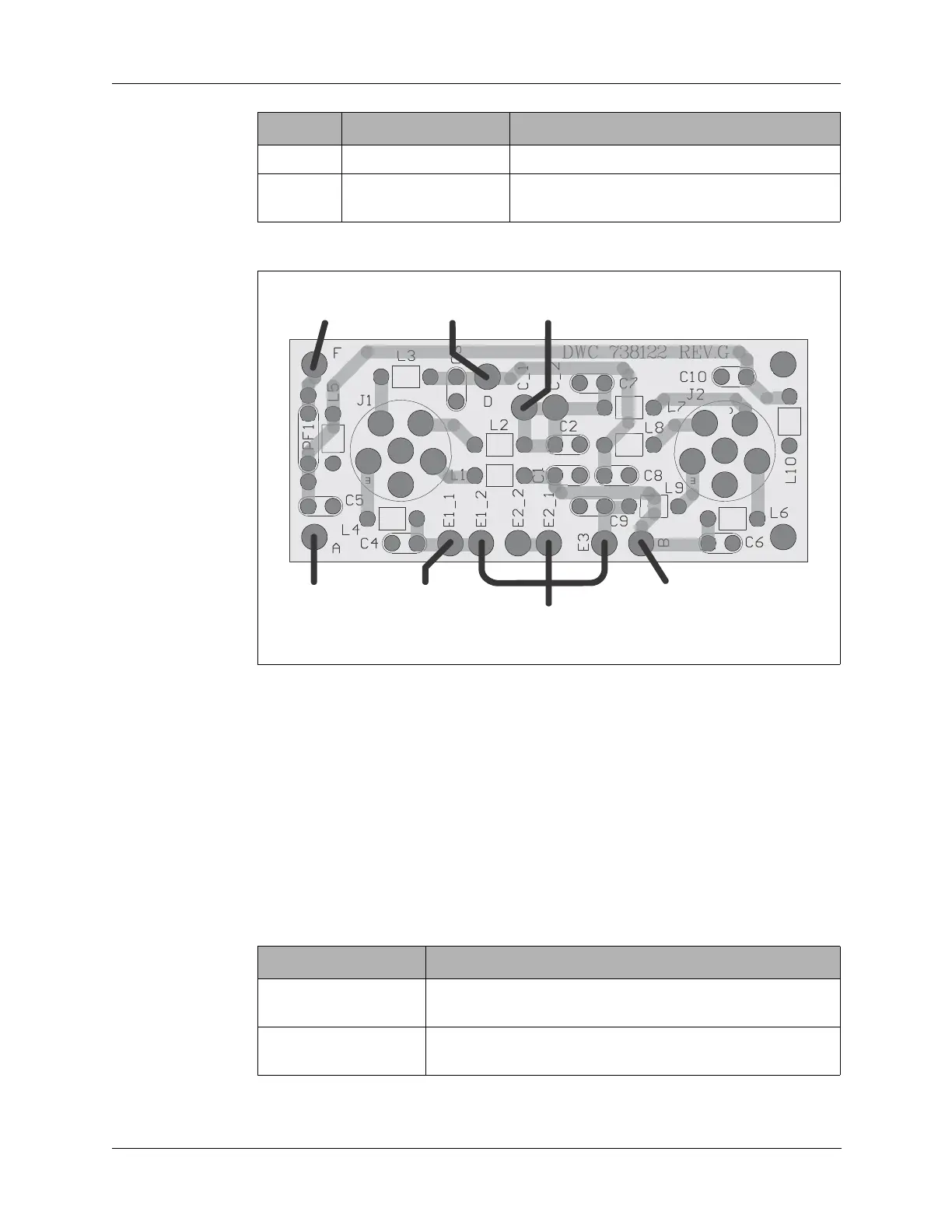
Figure 12-6 below shows the Audio connector board layout.
12.2.2 Accessory Connector
The front panel Accessory connector connects to external RF power
amplifiers RA100-12 and RA100-24, and antenna tuner RAT7000B through
the MT-1099A mobile mount to provide data and control to these devices.
The Accessory connector also allows the PRC1099A to connect with vehicle
mounts such as the MT1099A for 12V (MT1099A-12) and 24V
(MT-1099A-24) environments.
The Accessory connector cap includes a jumper that shorts pin F to pin E.
E CW KEY CW key tone input to the Processor board.
F +12V SW +12 VDC battery power switch through the
front panel Power switch.
Figure 12-6 Audio Connector Board Pinout
Pin Name Description
A
B
C
D
E
F
A
B
C
D
E
F
B. RX Audio to
Audio Filter Board
D. TX Audio from
Audio Filter Board
A. GND
F. +12V from
Junction Board
C. PTT to Accessory connector pin C
and to Processor Board
E1. CW Key to
Processor Board
E2. Handset to
Processor Board
(no longer used)
Table 12-3 Supported Accessory Devices
Device Description
MT-1099A-12 Vehicle adapter and mobile mount for 12V system with
integrated loud speaker.
MT-1099A-24 Vehicle adapter and mobile mount for 24V system with
integrated loud speaker.