13: Internal Options
PRC1099A-MS 13-5
Audio Buffers Audio buffer chip U17 provides buffering of the receive audio input and
transmit audio output. It also adjusts the input and output levels by adjusting
R10 and R11. For the location of adjustment points, refer to Figure 13-2 on
page 13-6.
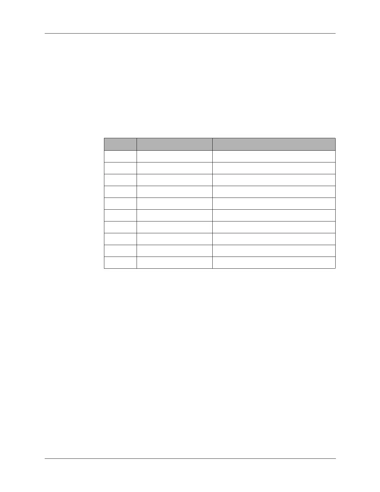
13.1.3 Connector Pin Assignments
J1 connects with Processor board J4 connector
The ALE board has the following interconnects with the transceiver.
Table 13-1 J1 Connector Pin Assignments
Pin Signal Description
1, 2 +5V 5 VDC from the Junction board
3, 4 DGND Digital ground
5, 6 AGND Analog ground
7-14 N/C No connection
15 KEYLINE ALE PTT input
16 ALEPTT ALE PTT output
17 SER CNTL RXD ALE serial data receive
18 SER CNTL TXD ALE serial data transmit
19 600 OHM RX AUDIO ALE receive audio
20 600 OHM TX AUDIO ALE transmit audio