14: Maintenance
14-10 PRC1099A-MS
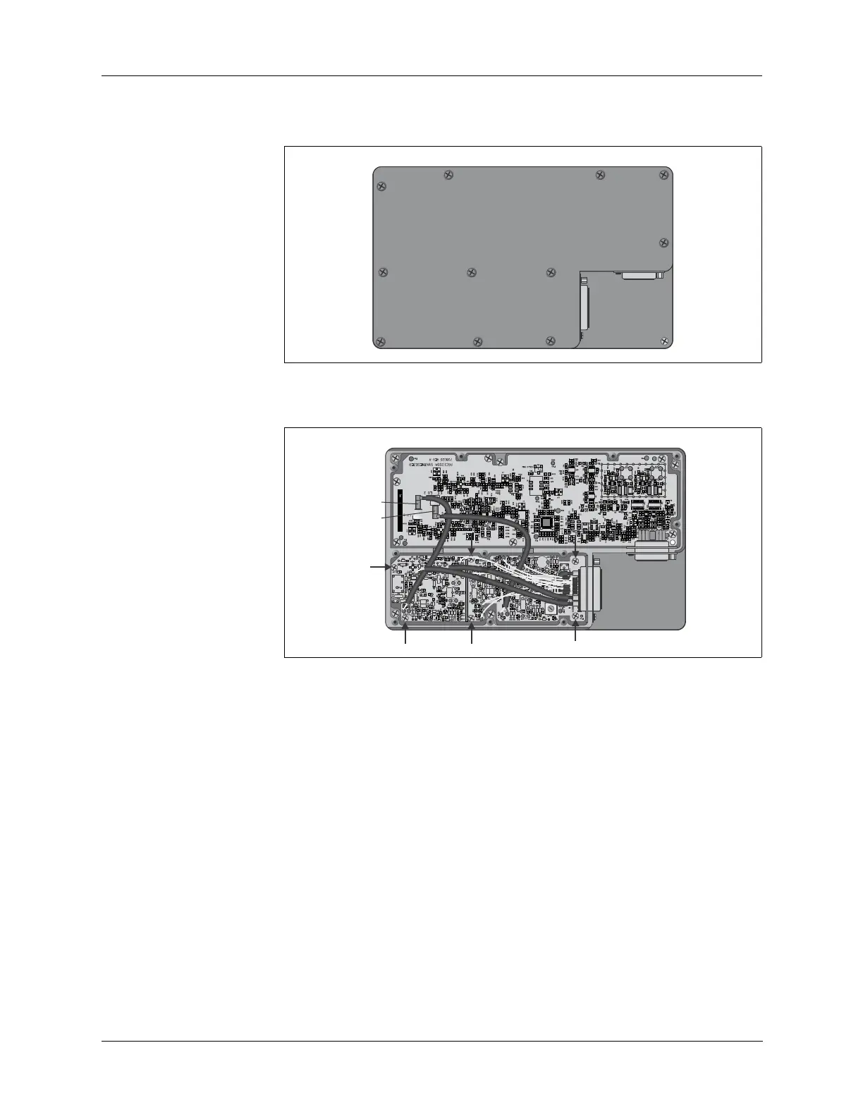
3. Remove the 11 flat head tray cover retaining screws and remove the
cover.
4. Disconnect the coax connectors J2 (LO1) and J3 (LO2) from the
Synthesizer board.
5. Remove the six mounting screws shown above and then lift the Mixer
board out of the tray.
6. Reverse this procedure to install the new Mixer board.
Remove and
Replace the
Synthesizer
Board
To remove and replace the Synthesizer board:
1. Disassemble the radio chassis (refer to “Chassis Disassembly” on page
14-4).
2. Disconnect the Synthesizer board multiple-pin connector J1.
3. Remove the 11 flat head tray cover retaining screws and remove the
cover.
4. Disconnect the coax connectors J2 (LO1) and J3 (LO2).
Mixer Board
J1
Synthesizer
Board J1
Mixer Board
J1
Synthesizer
Board J1
LO1
LO2