14: Maintenance
PRC1099A-MS 14-19
3. On the chassis side panel, use a DVM to probe the supply voltage test
points to verify that the +12V supply voltage is 12 VDC, the +8V and
R8 (in receive mode) are +8 VDC, and the +5V supply is 5 VDC.
4. Press PTT. Verify that the T8 line is +8 VDC.
The voltage regulators and voltage adjustment controls are located on
the Junction board, with the R8 and T8 clamps.
CAUTION: Correct operating voltages must be present
before checking the transceiver. Check the
power supply, wiring and board connections
before replacing the Audio or Processor boards.
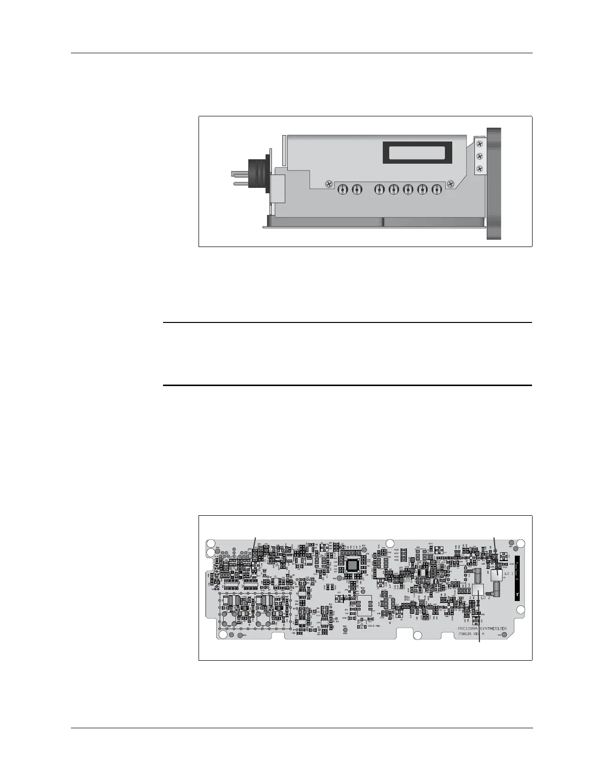
Synthesizer
Board
If the radio works correctly in either the transmit or receive mode, the
Synthesizer board is operating normally. To verify signal levels, make the
following measurements:
1. Remove the cover on the Mixer/Synthesizer assembly (refer to
“Remove and Replace the Synthesizer Board” on page 14-10) to
access the RF input and output connections on these boards.
2. Connect a frequency counter to 1st LO output (J2).
R8
T8
+5V
+8V
+12V
+8V ADJUST
+5V ADJUST
M2
PRC1099-M2
1650 IF MODULE